David Cuartielles with the help of DongHoo Kim, KeunGook Seok and Ahrum Kwon.
[Date and time]
2007년 11월 5일(월) pm 5:00 ~ 9:00 class section
2007년 11월 6일(화) pm 1:00 ~ 4:00 catch up section
Pm 5:00 ~ 9:00 class section
[Location]
아트센터 나비(Art Center_nabi) 원형극장
[Participants]
최대 15명 (Max. 15 participants)
[FEE]
15만원 (D.I.Y 키트 제공)
[Participants Requirements]
No special requirements are needed, however it is preferred if the participants have some knowledge about sound production. We encourage the participants to bring their own laptops, if they have one. They should bring headphones.
- understanding basic concepts of low level sound/noise production
-예술적 생산을 위한 오픈 툴 만들어 보기
-오픈소스 문화의 이해
-로우 레벨 사운드/ 노이즈 음악 제작의 이해
[Wokshop Outlines]
Day 1: PROTOTYPING
a)short introductory lecture: prototyping platforms, an overview of what exists and how it is used
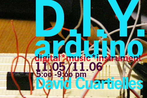
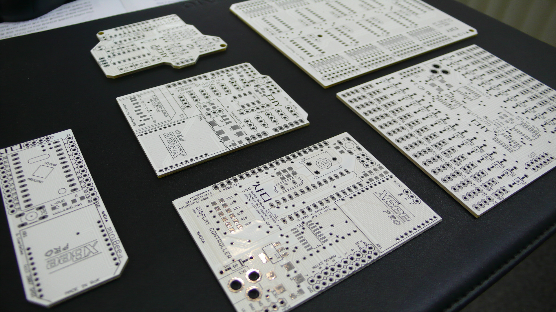
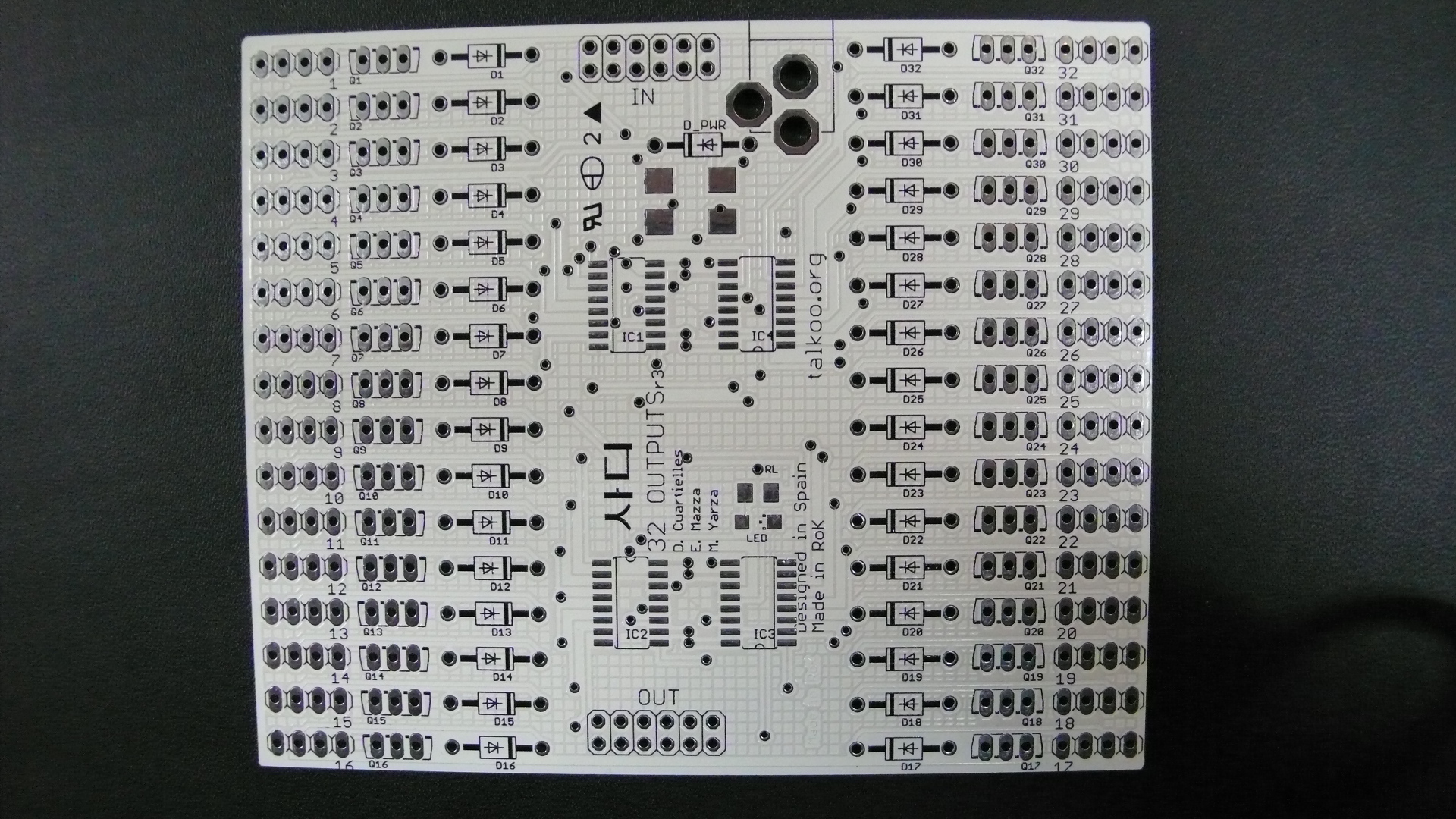
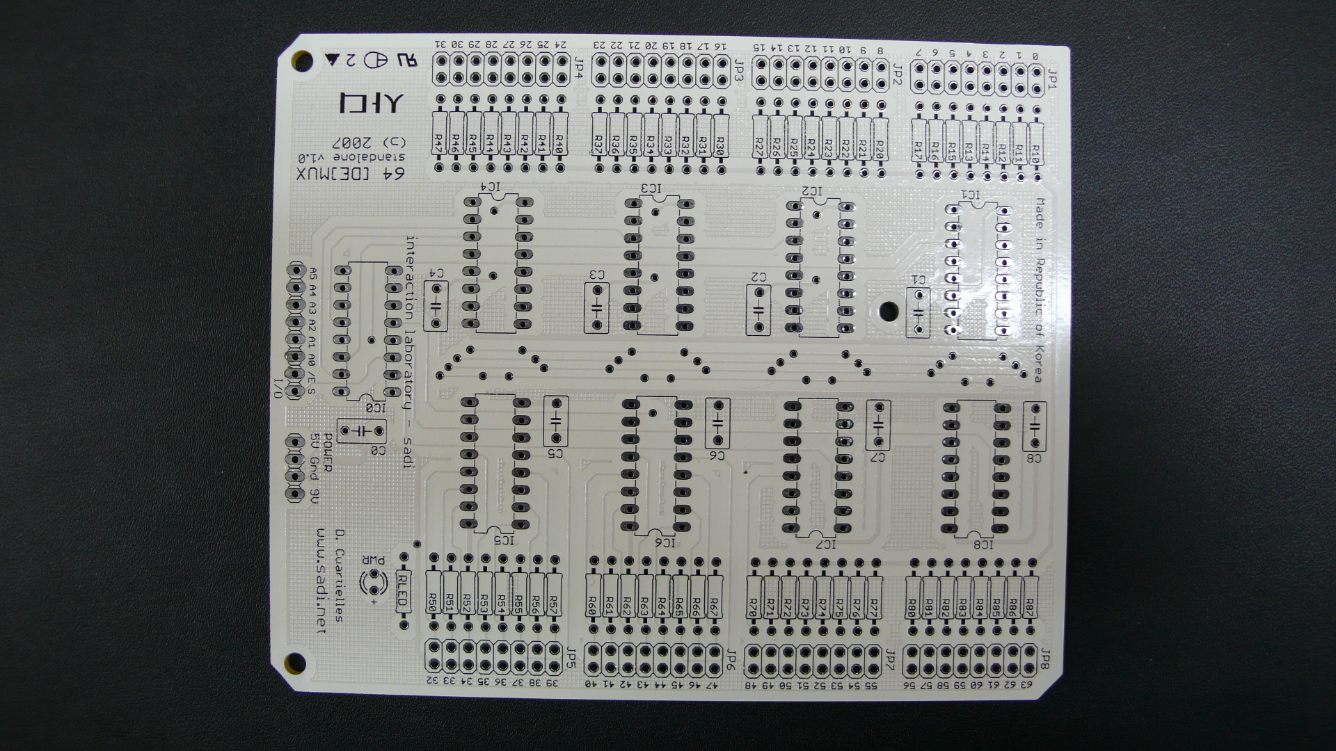
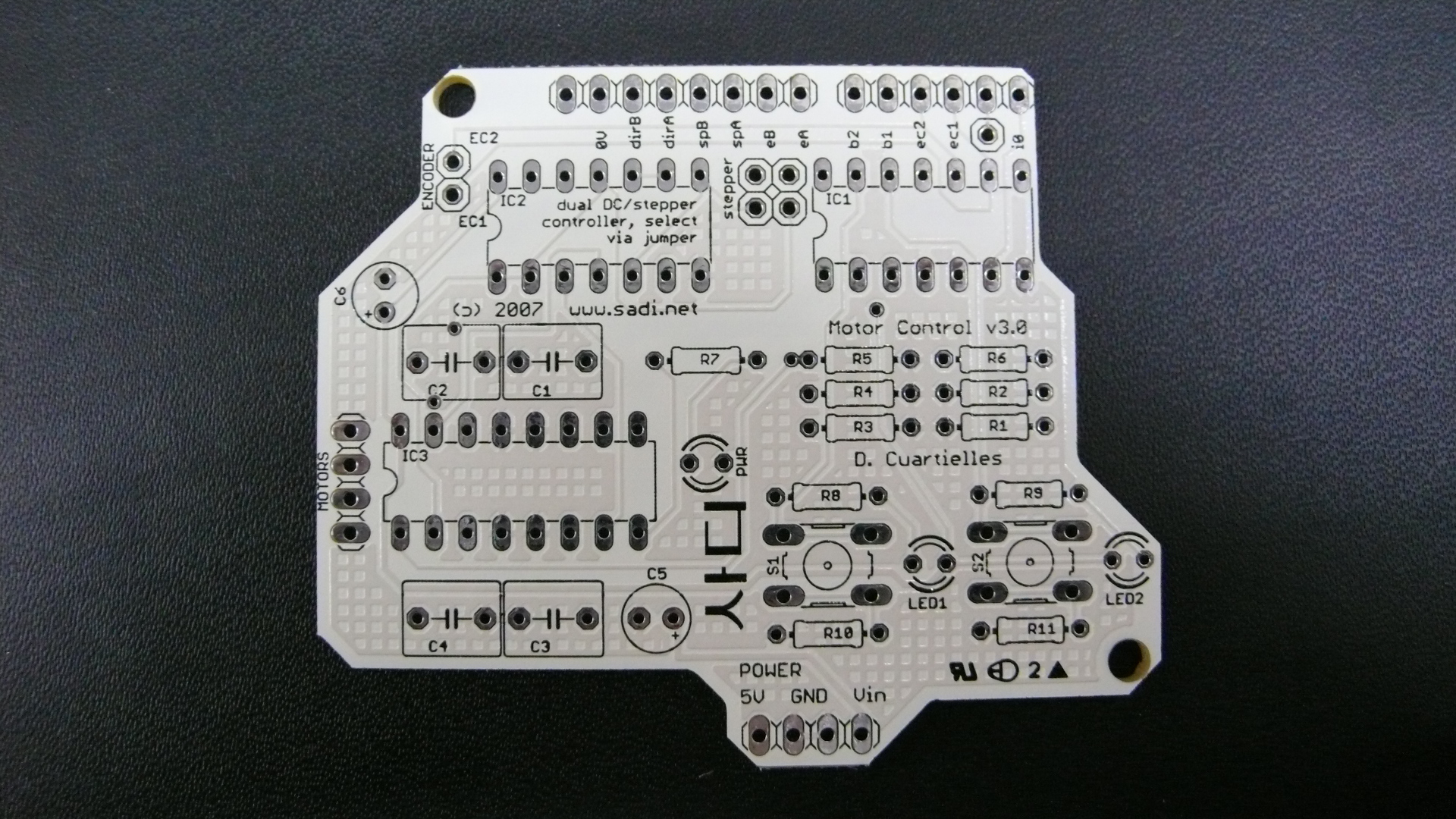
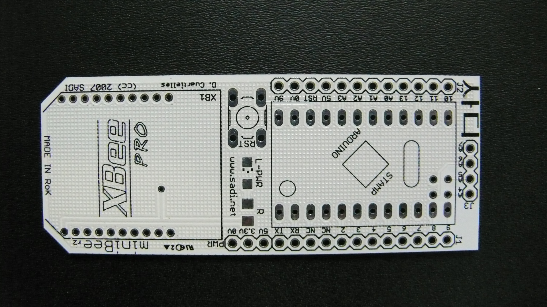
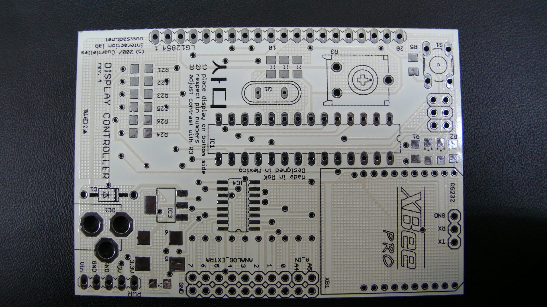
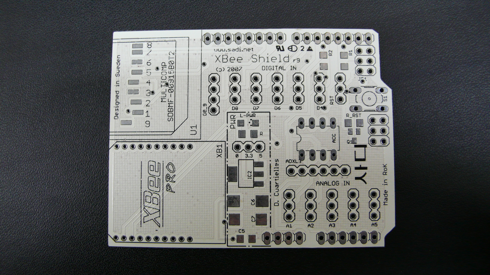
b)DIY Arduino board: Make your own Arduino-compatible board. Using components available at Seoul’s traditional electronic stores we will build home-brew Arduino compatible circuits that could be used for multiple applications.
This first session will introduce the participants to the creation of a basic I/O platform. With it they can create all sort of physical computing devices, interactive artifacts, and electronic art installations.
a)short sound lecture: 8-bit sound as in Nintendo, Commodore, and Nokia ringtones
b)DIY Digital Music Instruments: We will look into the creation of small music instruments that make use of our own homebrew Arduino board. Small interactive toys using buttons and knobs as interface will be produced.
c)presentation: the participants will make small sound performances, as short as 2 minutes to explain their results
The main topic of the day is the use of light as an expressive way of interaction. As examples of different light projects, we have seen a bunch of movies taken from different projects existing on the internet.
[Tabletalk by Eriksson, Sjunnesson, Gedin et al.]
[butterfly a German table lamp]
['Borg3D' an interesting 3D LED lamp]
[a NONO on the design business]
['DaTable' from The Netherlands]
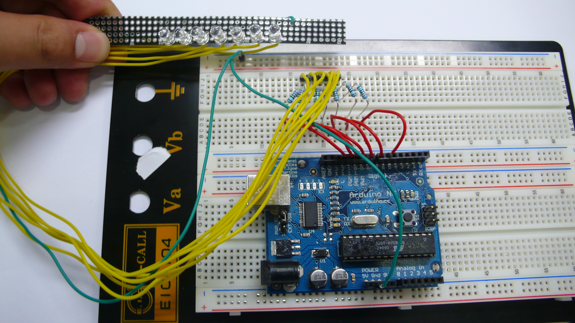
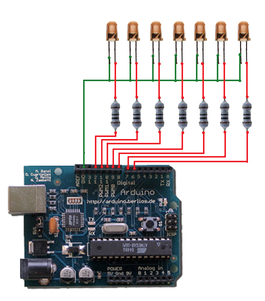
Code example for a P.O.V. device
An array of LEDs changing their values in time at a high speed, can simulate to be many more thanks to the P.O.V. cognitive effect.
int ledPin[7] = {6,7,8,9,10,11,12,}; int matrix[7][12] = {0,1,1,1,0,0,0,1,0,0,0,1, 1,0,0,0,1,0,0,1,0,0,1,0, 1,0,0,0,1,0,0,1,0,1,0,0, 1,0,0,0,1,0,0,1,1,1,0,0, 1,0,0,0,1,0,0,1,0,0,1,0, 1,0,0,0,1,0,0,1,0,0,0,1, 0,1,1,1,0,0,0,1,0,0,0,1 }; int i,j;
12번/13번 핀에 위와 동일한 구조의 회로를 하나 더 만들어서 연결해야한다. (두개의 LED를 연동 시키기 위해서)
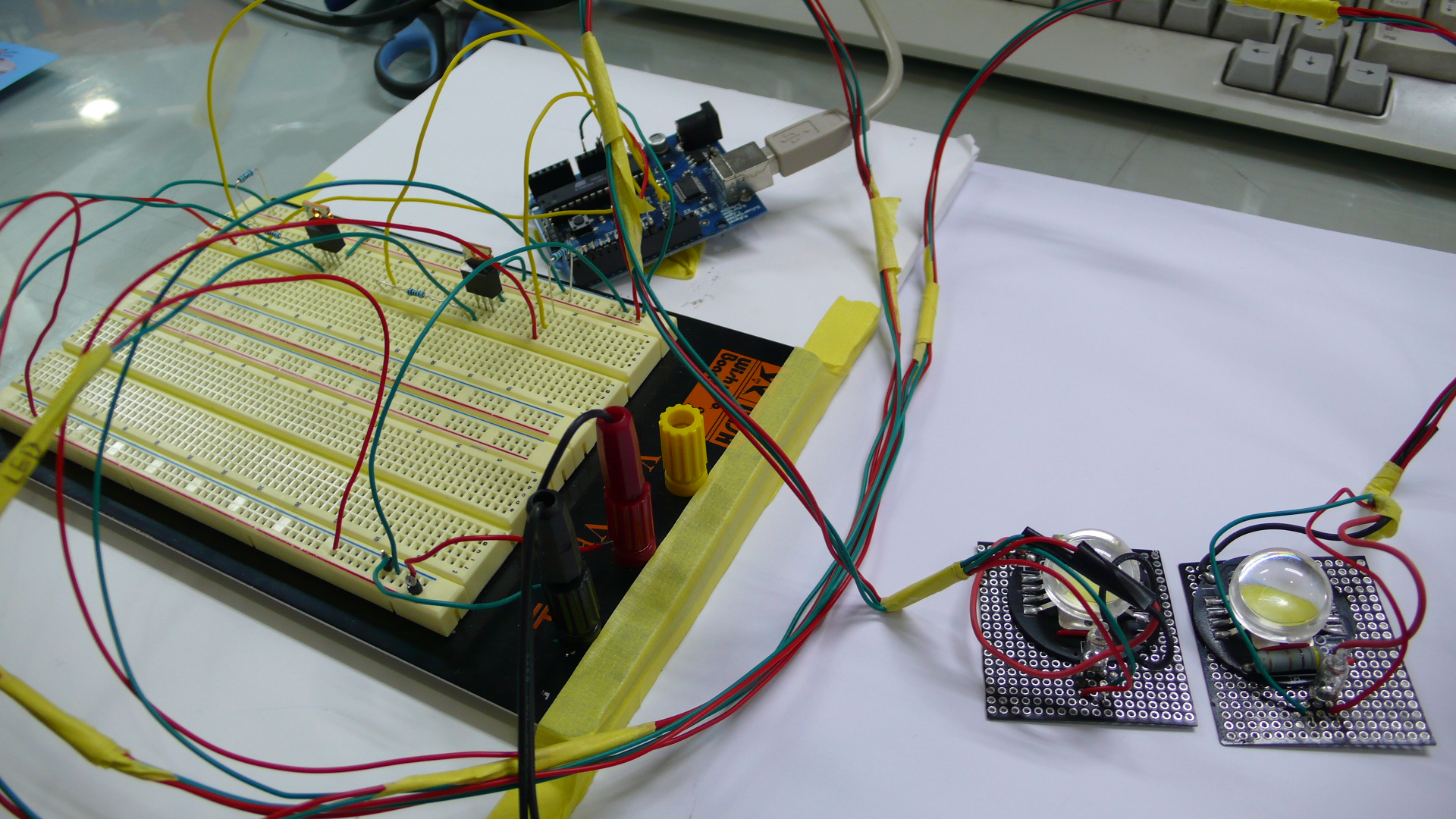
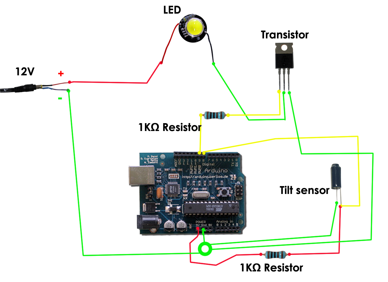
틸트 센서의 기울기에 따라 전구의 불빛에 변화를 줄 수 있도록 만들었다. 틸트 센서에서 기울기 값을 아듀이노 보드로 보내고 아듀이노 보드는 트랜지스터에 그 시그널을 보낸다. 트랜지스터는 그 값에 따라 LED를 on/off 시킨다. (트랜지스터는 스위치와 같은 역할을 한다)
With the use of Tilt sensors and powerful LEDs we can simulate a transfer of light between two different devices. They can be used to illuminate spaces, location markers, energy indicators ...
int tiltInA = 12; // Tilt 1 connected to digital pin 9 int tiltInB = 13; // Tilt 2 connected to digital pin 9
int pwmOutA = 9; // MOSFET connected to analog pin 3 int pwmOutB = 10; // MOSFET connected to analog pin 3
int amountOfA = 255; // variable to store the read value int amountOfB = 0;
if(amountOfB < 0){ amountOfB = 0; amountOfA = 255; //don't need to check A, because A + B = always 255 } }
//analogWrite(ledPin, val / 4); // analogRead values go from 0 to 1023, analogWrite values from 0 to 255 analogWrite(pwmOutA, amountOfA); Serial.println(amountOfA, DEC); delay(5); analogWrite(pwmOutB, amountOfB); Serial.println(amountOfB, DEC); delay(5);
}
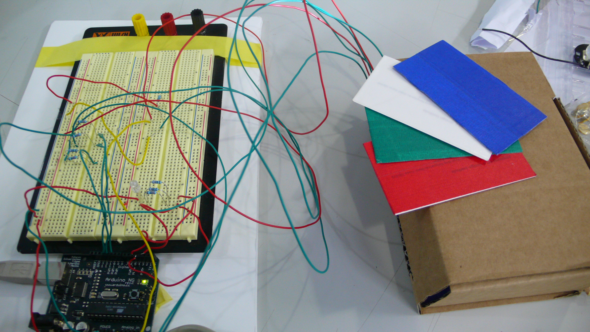
Code example for a color sensor
Sensing colors is just about measuring the amount of each component of light. Let's see how accurate we can become in reading colors from different objects and expressing them through RGB LEDs.
// default change values as in the lab
// recalibrate for you own system
//                      R    G    B    W
int matrixRGB[3][4] = {680, 643, 578, 375,
                       759, 631, 720, 360,
                       254, 591, 603, 210 };
// safety margin
int sM = 30;

// LED pin out
int ledPinIn_R = 12;
int ledPinIn_B = 11;
int ledPinIn_G = 10;

int ledPinOut_R = 5;
int ledPinOut_B = 4;
int ledPinOut_G = 3;

// analog sensor (LDR)
int analogPin = 0;
int val_R = 0;
int val_G = 0;
int val_B = 0;

// start up calibration
int cal_R = 0;
int cal_G = 0;
int cal_B = 0;

void lightBLUE() {
  digitalWrite(ledPinOut_R, HIGH);
  digitalWrite(ledPinOut_G, HIGH);
  digitalWrite(ledPinOut_B, LOW);
  Serial.println("it is BLUE");
}

void lightRED() {
  digitalWrite(ledPinOut_R, LOW);
  digitalWrite(ledPinOut_G, HIGH);
  digitalWrite(ledPinOut_B, HIGH);
  Serial.println("it is RED");
}

void lightGREEN() {
  digitalWrite(ledPinOut_R, HIGH);
  digitalWrite(ledPinOut_G, LOW);
  digitalWrite(ledPinOut_B, HIGH);
  Serial.println("it is GREEN");
}

void lightWHITE() {
  digitalWrite(ledPinOut_R, LOW);
  digitalWrite(ledPinOut_G, LOW);
  digitalWrite(ledPinOut_B, LOW);
  Serial.println("it is WHITE");
}

void noLight() {
  digitalWrite(ledPinOut_R, HIGH);
  digitalWrite(ledPinOut_G, HIGH);
  digitalWrite(ledPinOut_B, HIGH);
}

void demoLight() {
  for (int i = 0; i < 3; i++) {
  lightBLUE();
  delay(100);
  lightGREEN();
  delay(100);
  lightRED();
  delay(100);
  lightWHITE();
  delay(100);
  }
  noLight();
}

void calibrate() {
  for(int c = 0; c < 10; c++) {
  //RED
  digitalWrite(ledPinIn_R, LOW);
  digitalWrite(ledPinIn_G, HIGH);
  digitalWrite(ledPinIn_B, HIGH);
  delay(100);
  if (c > 0) {
  cal_R += analogRead(analogPin);
  cal_R /= 2;
  } else {
  cal_R = analogRead(analogPin);
  }
  delay(50);

  //GREEN
  digitalWrite(ledPinIn_R, HIGH);
  digitalWrite(ledPinIn_G, LOW);
  digitalWrite(ledPinIn_B, HIGH);
  delay(100);
  if (c > 0) {
  cal_G += analogRead(analogPin);
  cal_G /= 2;
  } else {
  cal_G = analogRead(analogPin);
  }
  delay(50);

  //BLUE
  digitalWrite(ledPinIn_R, HIGH);
  digitalWrite(ledPinIn_G, HIGH);
  digitalWrite(ledPinIn_B, LOW);
  delay(100);
  if (c > 0) {
  cal_B += analogRead(analogPin);
  cal_B /= 2;
  } else {
  cal_B = analogRead(analogPin);
  }
  delay(50);
  }
}

void setup(){
  pinMode(ledPinIn_R, OUTPUT);
  pinMode(ledPinIn_G, OUTPUT);
  pinMode(ledPinIn_B, OUTPUT);

  pinMode(ledPinOut_R, OUTPUT);
  pinMode(ledPinOut_G, OUTPUT);
  pinMode(ledPinOut_B, OUTPUT);

  Serial.begin(9600);

  // calibrate the sensors and print out the values
  demoLight();
  calibrate();
  Serial.println("************************");
  Serial.print("RED calibration: ");
  Serial.println(cal_R, DEC);
  Serial.print("GREEN calibration: ");
  Serial.println(cal_G, DEC);
  Serial.print("BLUE calibration: ");
  Serial.println(cal_B, DEC);
  Serial.println("************************");

}

void loop(){

  //RED
  digitalWrite(ledPinIn_R, LOW);
  digitalWrite(ledPinIn_G, HIGH);
  digitalWrite(ledPinIn_B, HIGH);
  delay(100);
  val_R = analogRead(analogPin);
  //Serial.print("RED ");
  //Serial.println(val_R, DEC);
  delay(100);

  //GREEN
  digitalWrite(ledPinIn_R, HIGH);
  digitalWrite(ledPinIn_G, LOW);
  digitalWrite(ledPinIn_B, HIGH);
  delay(100);
  val_G = analogRead(analogPin);
  //Serial.print("GREEN ");
  //Serial.println(val_G, DEC);
  delay(100);

  //BLUE
  digitalWrite(ledPinIn_R, HIGH);
  digitalWrite(ledPinIn_G, HIGH);
  digitalWrite(ledPinIn_B, LOW);
  delay(100);
  val_B = analogRead(analogPin);
  //Serial.print("BLUE ");
  //Serial.println(val_B, DEC);
  delay(100);

    if (val_R < matrixRGB[0][3] + sM && val_G < matrixRGB[1][3] +
                                sM && val_B < matrixRGB[2][3] + sM)
          lightWHITE();
    else if (val_R < matrixRGB[0][2] + sM && val_G < matrixRGB[1][2] +
                                sM && val_B < matrixRGB[2][2] + sM)
          lightBLUE();
    else if (val_R < matrixRGB[0][1] + sM && val_G < matrixRGB[1][1] +
                                 sM && val_B < matrixRGB[2][1] + sM)
          lightGREEN();
    else if (val_R < matrixRGB[0][0] + sM && val_G < matrixRGB[1][0] +
                                 sM && val_B < matrixRGB[2][0] + sM)
          lightRED();
    else
          noLight();

  delay(200);

}
sadi (samsung art and design institute)는 2007년 9월부터 인터랙션 디자인 랩 주관으로 디자이너와 아티스트가 함께 참여하는 sadi open laboratory sessions (S.O.L)을 개설합니다.
인터랙션 디자인, 인터페이스 디자인 및 웨어러블 컴퓨팅에 관심있는 sadi 재학생, 교수님, 피지컬 컴퓨팅 작업에 어려움을 겪고 있거나 Arduino 보드와 여러 다른 프로그램을 연동시키고자 하는 많은 사람들이 함께 협력하여 문제를 해결해 나갈 수 있는 자리를 마련하고자 준비되었습니다.
방금 완성한 작품을 보다 많은 사람들과 함께 나누고 싶으시다면 S.O.L이 해답이 될 수 있을 것입니다. S.O.L은 Arduino group의 일원이며 현재 sadi product design과 초빙 교수로 있는 Prof. D.Cuartielles의 주도로 운영되며 인터랙션 디자이너들 간의 활발한 토론의 장이되고 동시에 open tools의 저변확대에 기여하기를 희망합니다.
S.O.L은 매주 목요일 오후 7시부터 자유롭게 진행되며 희망하시는 모든 분들은 무료로 참여하실 수 있습니다. 참여를 희망하시는 분들은 이 곳 사이트에 참여의사를 남겨주시거나, cakepower@gmail.com 에게 메일을 보내주시기만 하면 됩니다.
Sadi Open Laboratory (S.O.L) 는 새로운 아이디어를 찾고 있는 분들이 모여 서로 토론하고, 자신의 경험을 공유하고, 발전시켜가는 공간이 될 것입니다.