

Lighting Control
Technical References/Lighting 2007. 9. 13. 16:48Today's topic
The main topic of the day is the use of light as an expressive way of interaction. As examples of different light projects, we have seen a bunch of movies taken from different projects existing on the internet.[Tabletalk by Eriksson, Sjunnesson, Gedin et al.]
[butterfly a German table lamp]
['Borg3D' an interesting 3D LED lamp]
[a NONO on the design business]
['DaTable' from The Netherlands]
Code example for a P.O.V. device
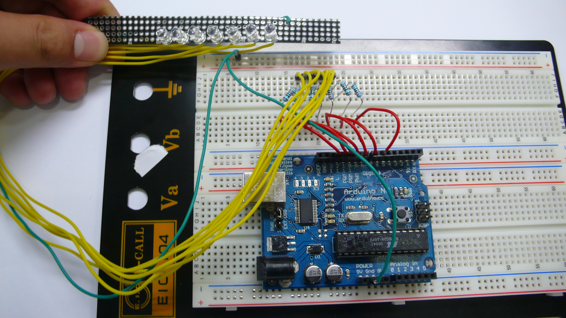
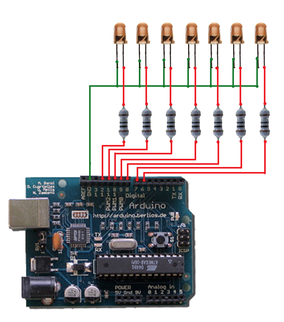
An array of LEDs changing their values in time at a high speed, can simulate to be many more thanks to the P.O.V. cognitive effect.
int ledPin[7] = {6,7,8,9,10,11,12,};
int matrix[7][12] = {0,1,1,1,0,0,0,1,0,0,0,1,
1,0,0,0,1,0,0,1,0,0,1,0,
1,0,0,0,1,0,0,1,0,1,0,0,
1,0,0,0,1,0,0,1,1,1,0,0,
1,0,0,0,1,0,0,1,0,0,1,0,
1,0,0,0,1,0,0,1,0,0,0,1,
0,1,1,1,0,0,0,1,0,0,0,1 };
int i,j;
void setup(){
for(i=0; i<7; i++){
pinMode(ledPin[i], OUTPUT);
}
}
void loop(){
for(i=0; i<12; i++){
for(j=0; j<7; j++){
digitalWrite(ledPin[j], matrix[j][i]);
}
delay(5);
}
for(i=11; i>=0; i--){
for(j=0; j<7; j++){
digitalWrite(ledPin[j], matrix[j][i]);
}
delay(5);
}
}
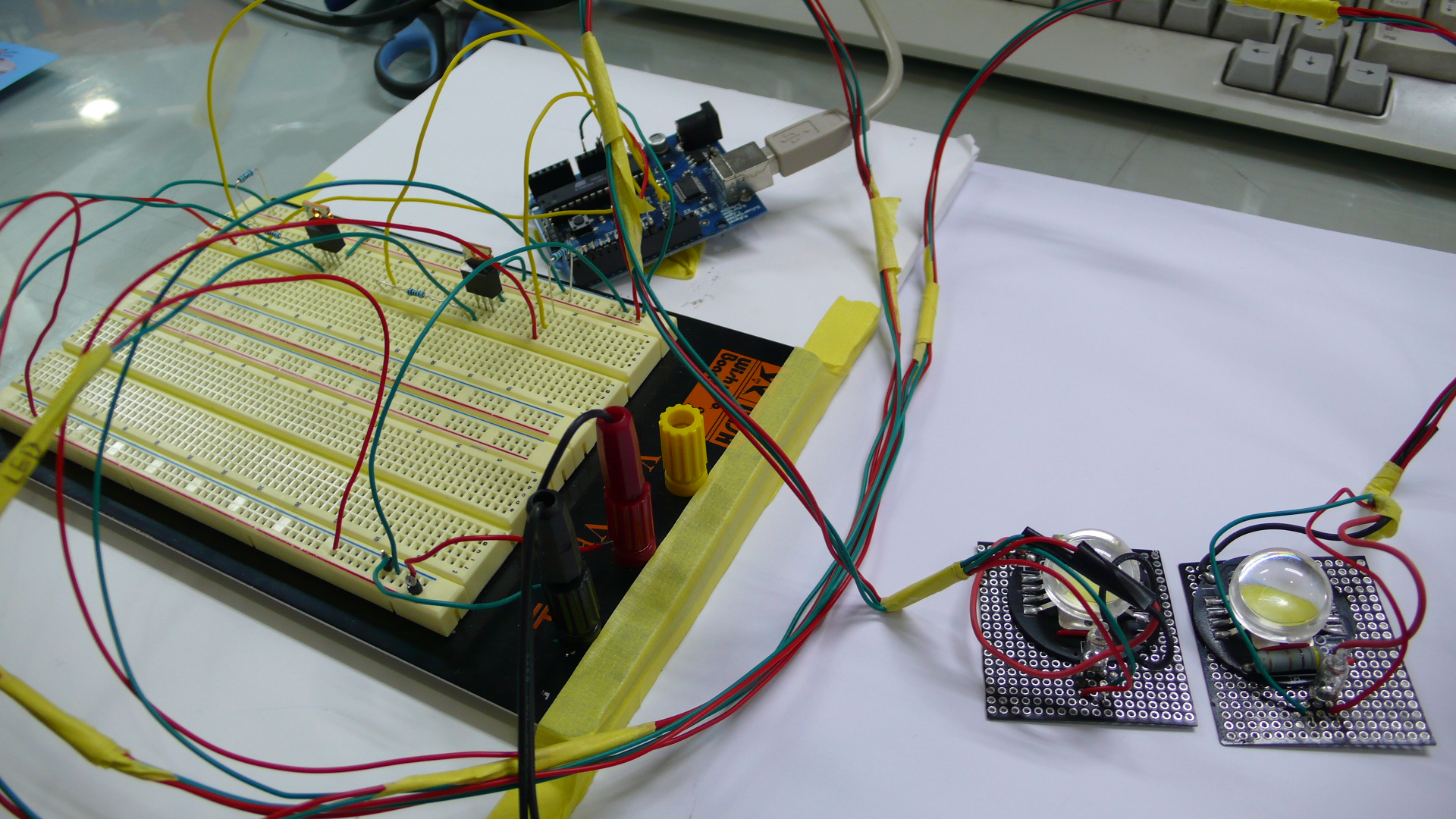
Code example for a light transfer
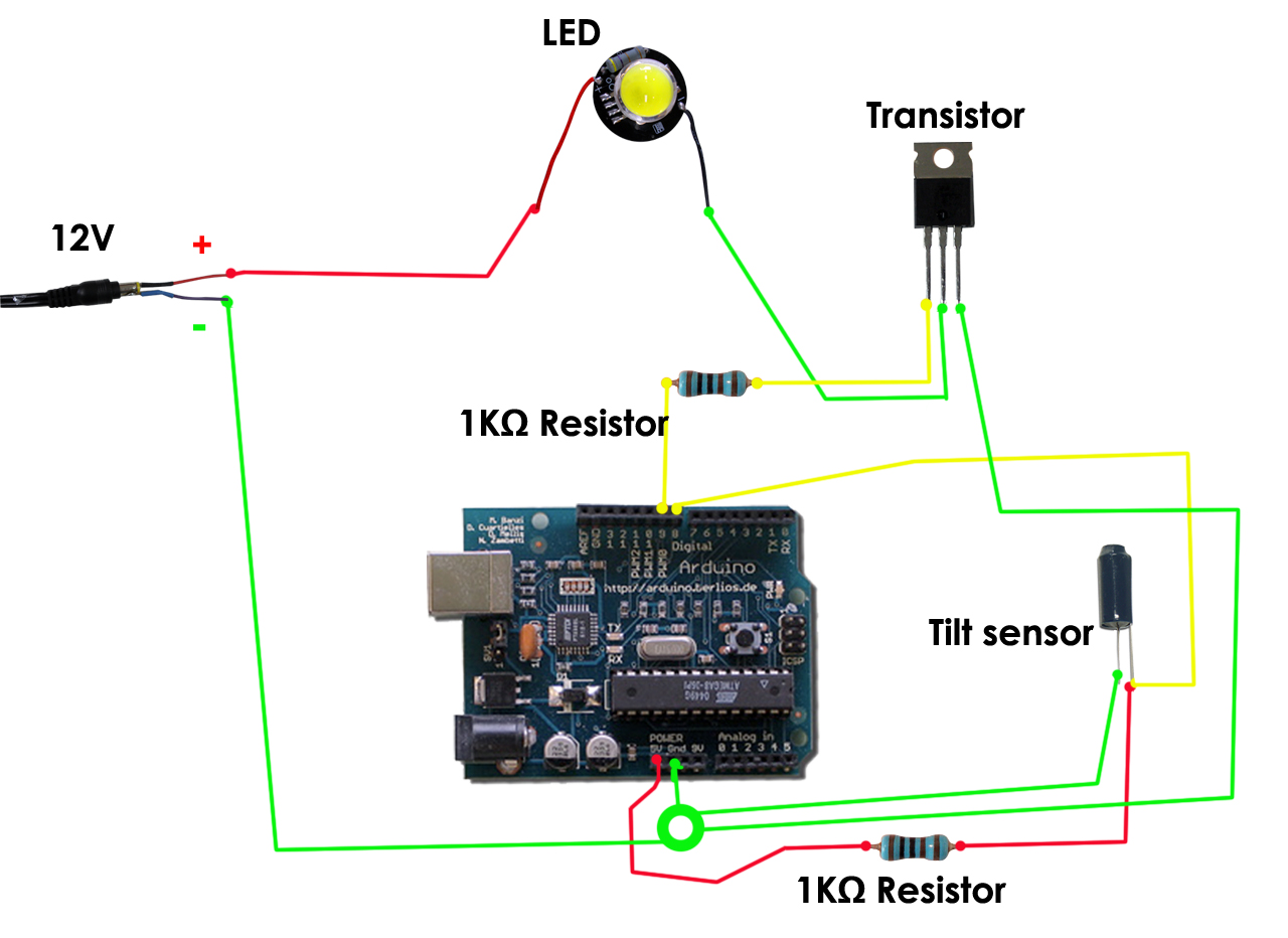
12번/13번 핀에 위와 동일한 구조의 회로를 하나 더 만들어서 연결해야한다.
(두개의 LED를 연동 시키기 위해서)
틸트 센서의 기울기에 따라 전구의 불빛에 변화를 줄 수 있도록 만들었다.
틸트 센서에서 기울기 값을 아듀이노 보드로 보내고
아듀이노 보드는 트랜지스터에 그 시그널을 보낸다.
트랜지스터는 그 값에 따라 LED를 on/off 시킨다.
(트랜지스터는 스위치와 같은 역할을 한다)
With the use of Tilt sensors and powerful LEDs we can simulate a transfer of light between two different devices. They can be used to illuminate spaces, location markers, energy indicators ...
int tiltInA = 12; // Tilt 1 connected to digital pin 9
int tiltInB = 13; // Tilt 2 connected to digital pin 9
int pwmOutA = 9; // MOSFET connected to analog pin 3
int pwmOutB = 10; // MOSFET connected to analog pin 3
int amountOfA = 255; // variable to store the read value
int amountOfB = 0;
int tiltValueA = 0;
int tiltValueB = 0;
void setup()
{
Serial.begin(9600);
pinMode(pwmOutA, OUTPUT);
pinMode(pwmOutB, OUTPUT);
pinMode(tiltInA, INPUT);
pinMode(tiltInB, INPUT);
}
void loop()
{
tiltValueA = digitalRead(tiltInA);
if(tiltValueA == HIGH){ //tilt state
if(amountOfA > 150){
amountOfA = amountOfA - 1;
amountOfB = amountOfB + 1;
}else{
amountOfA = amountOfA - 2;
amountOfB = amountOfB + 2;
}
if(amountOfA < 0 ){
amountOfA = 0;
amountOfB = 255; //don't need to check B, because A + B = always 255
}
}
tiltValueB = digitalRead(tiltInB);
if(tiltValueB == HIGH){ //tilt state
if(amountOfB > 150){
amountOfB = amountOfB - 1;
amountOfA = amountOfA + 1;
}else{
amountOfB = amountOfB - 2;
amountOfA = amountOfA + 2;
}
if(amountOfB < 0){
amountOfB = 0;
amountOfA = 255; //don't need to check A, because A + B = always 255
}
}
//analogWrite(ledPin, val / 4);
// analogRead values go from 0 to 1023, analogWrite values from 0 to 255
analogWrite(pwmOutA, amountOfA);
Serial.println(amountOfA, DEC);
delay(5);
analogWrite(pwmOutB, amountOfB);
Serial.println(amountOfB, DEC);
delay(5);
}
Code example for a color sensor
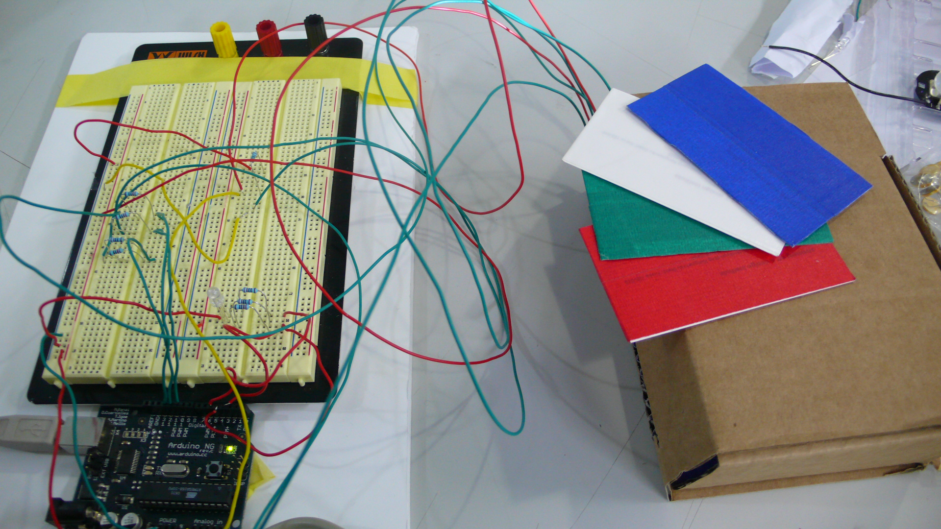
Sensing colors is just about measuring the amount of each component of light. Let's see how accurate we can become in reading colors from different objects and expressing them through RGB LEDs.
// default change values as in the lab
// recalibrate for you own system
//                      R    G    B    W
int matrixRGB[3][4] = {680, 643, 578, 375,
                       759, 631, 720, 360,
                       254, 591, 603, 210 };
// safety margin
int sM = 30;

// LED pin out
int ledPinIn_R = 12;
int ledPinIn_B = 11;
int ledPinIn_G = 10;

int ledPinOut_R = 5;
int ledPinOut_B = 4;
int ledPinOut_G = 3;

// analog sensor (LDR)
int analogPin = 0;
int val_R = 0;
int val_G = 0;
int val_B = 0;

// start up calibration
int cal_R = 0;
int cal_G = 0;
int cal_B = 0;

void lightBLUE() {
  digitalWrite(ledPinOut_R, HIGH);
  digitalWrite(ledPinOut_G, HIGH);
  digitalWrite(ledPinOut_B, LOW);
  Serial.println("it is BLUE");
}

void lightRED() {
  digitalWrite(ledPinOut_R, LOW);
  digitalWrite(ledPinOut_G, HIGH);
  digitalWrite(ledPinOut_B, HIGH);
  Serial.println("it is RED");
}

void lightGREEN() {
  digitalWrite(ledPinOut_R, HIGH);
  digitalWrite(ledPinOut_G, LOW);
  digitalWrite(ledPinOut_B, HIGH);
  Serial.println("it is GREEN");
}

void lightWHITE() {
  digitalWrite(ledPinOut_R, LOW);
  digitalWrite(ledPinOut_G, LOW);
  digitalWrite(ledPinOut_B, LOW);
  Serial.println("it is WHITE");
}

void noLight() {
  digitalWrite(ledPinOut_R, HIGH);
  digitalWrite(ledPinOut_G, HIGH);
  digitalWrite(ledPinOut_B, HIGH);
}

void demoLight() {
  for (int i = 0; i < 3; i++) {
  lightBLUE();
  delay(100);
  lightGREEN();
  delay(100);
  lightRED();
  delay(100);
  lightWHITE();
  delay(100);
  }
  noLight();
}

void calibrate() {
  for(int c = 0; c < 10; c++) {
  //RED
  digitalWrite(ledPinIn_R, LOW);
  digitalWrite(ledPinIn_G, HIGH);
  digitalWrite(ledPinIn_B, HIGH);
  delay(100);
  if (c > 0) {
  cal_R += analogRead(analogPin);
  cal_R /= 2;
  } else {
  cal_R = analogRead(analogPin);
  }
  delay(50);

  //GREEN
  digitalWrite(ledPinIn_R, HIGH);
  digitalWrite(ledPinIn_G, LOW);
  digitalWrite(ledPinIn_B, HIGH);
  delay(100);
  if (c > 0) {
  cal_G += analogRead(analogPin);
  cal_G /= 2;
  } else {
  cal_G = analogRead(analogPin);
  }
  delay(50);

  //BLUE
  digitalWrite(ledPinIn_R, HIGH);
  digitalWrite(ledPinIn_G, HIGH);
  digitalWrite(ledPinIn_B, LOW);
  delay(100);
  if (c > 0) {
  cal_B += analogRead(analogPin);
  cal_B /= 2;
  } else {
  cal_B = analogRead(analogPin);
  }
  delay(50);
  }
}

void setup(){
  pinMode(ledPinIn_R, OUTPUT);
  pinMode(ledPinIn_G, OUTPUT);
  pinMode(ledPinIn_B, OUTPUT);

  pinMode(ledPinOut_R, OUTPUT);
  pinMode(ledPinOut_G, OUTPUT);
  pinMode(ledPinOut_B, OUTPUT);

  Serial.begin(9600);

  // calibrate the sensors and print out the values
  demoLight();
  calibrate();
  Serial.println("************************");
  Serial.print("RED calibration: ");
  Serial.println(cal_R, DEC);
  Serial.print("GREEN calibration: ");
  Serial.println(cal_G, DEC);
  Serial.print("BLUE calibration: ");
  Serial.println(cal_B, DEC);
  Serial.println("************************");

}

void loop(){

  //RED
  digitalWrite(ledPinIn_R, LOW);
  digitalWrite(ledPinIn_G, HIGH);
  digitalWrite(ledPinIn_B, HIGH);
  delay(100);
  val_R = analogRead(analogPin);
  //Serial.print("RED ");
  //Serial.println(val_R, DEC);
  delay(100);

  //GREEN
  digitalWrite(ledPinIn_R, HIGH);
  digitalWrite(ledPinIn_G, LOW);
  digitalWrite(ledPinIn_B, HIGH);
  delay(100);
  val_G = analogRead(analogPin);
  //Serial.print("GREEN ");
  //Serial.println(val_G, DEC);
  delay(100);

  //BLUE
  digitalWrite(ledPinIn_R, HIGH);
  digitalWrite(ledPinIn_G, HIGH);
  digitalWrite(ledPinIn_B, LOW);
  delay(100);
  val_B = analogRead(analogPin);
  //Serial.print("BLUE ");
  //Serial.println(val_B, DEC);
  delay(100);

    if (val_R < matrixRGB[0][3] + sM && val_G < matrixRGB[1][3] +
                                sM && val_B < matrixRGB[2][3] + sM)
          lightWHITE();
    else if (val_R < matrixRGB[0][2] + sM && val_G < matrixRGB[1][2] +
                                sM && val_B < matrixRGB[2][2] + sM)
          lightBLUE();
    else if (val_R < matrixRGB[0][1] + sM && val_G < matrixRGB[1][1] +
                                 sM && val_B < matrixRGB[2][1] + sM)
          lightGREEN();
    else if (val_R < matrixRGB[0][0] + sM && val_G < matrixRGB[1][0] +
                                 sM && val_B < matrixRGB[2][0] + sM)
          lightRED();
    else
          noLight();

  delay(200);

}