DIY Arduino Digital Music Instruments
News/Events 2007. 10. 30. 01:12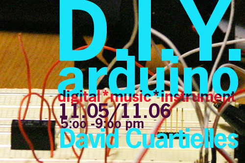
Nabi_Academy 2007 단기 워크샵
DIY Arduino Digital Music Instruments
[Facilitators]
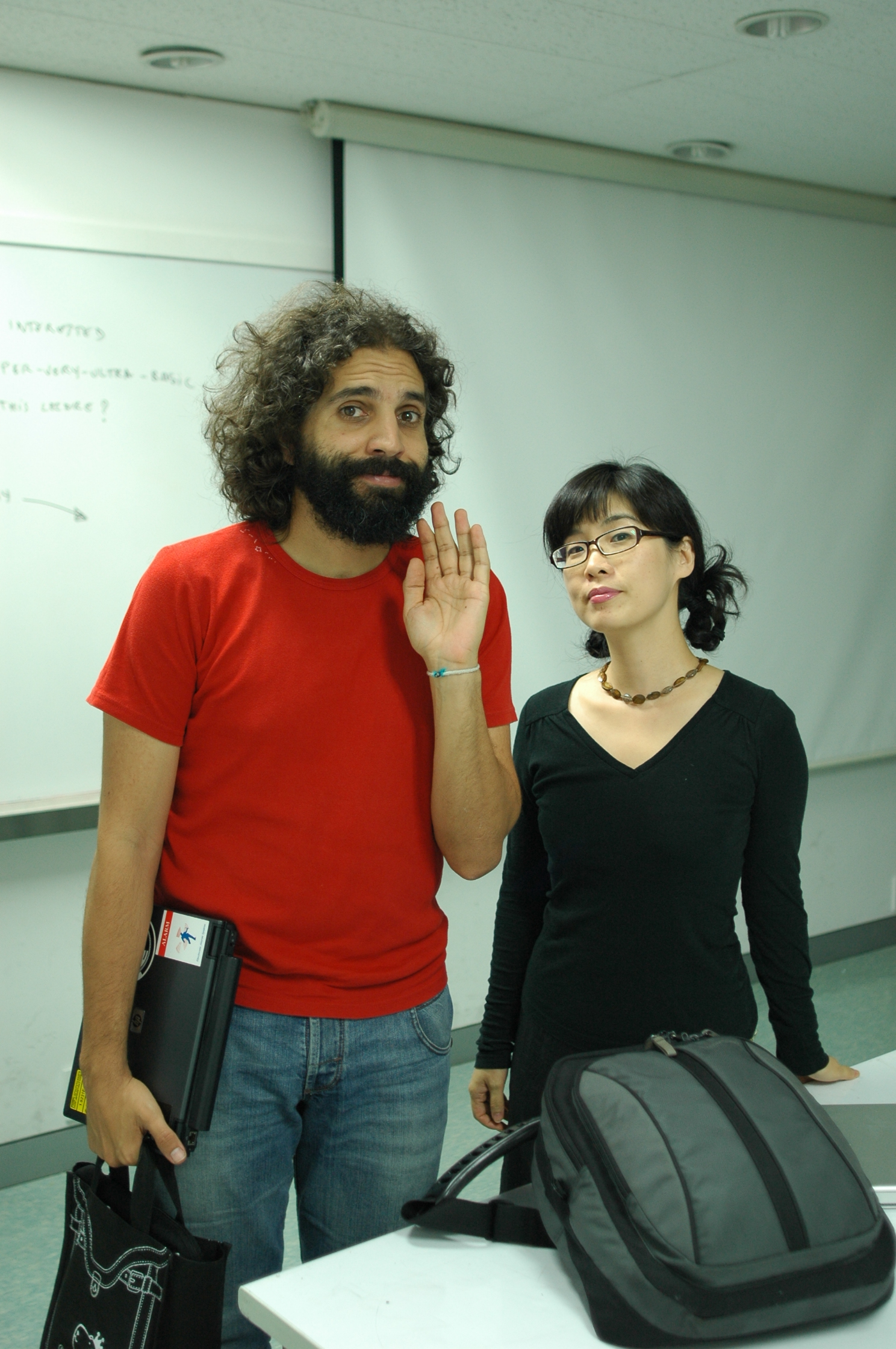
David Cuartielles with the help of DongHoo Kim, KeunGook Seok and Ahrum Kwon.
[Date and time]
2007년 11월 5일(월) pm 5:00 ~ 9:00 class section
2007년 11월 6일(화) pm 1:00 ~ 4:00 catch up section
Pm 5:00 ~ 9:00 class section
[Location]
아트센터 나비(Art Center_nabi) 원형극장
[Participants]
최대 15명 (Max. 15 participants)
[FEE]
15만원 (D.I.Y 키트 제공)
[Participants Requirements]
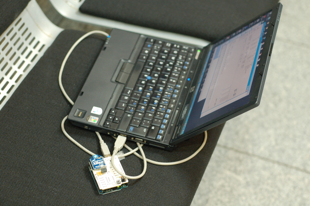
No special requirements are needed, however it is preferred if the participants have some knowledge about sound production. We encourage the participants to bring their own laptops, if they have one. They should bring headphones.
참가자 필요 사항 : 사운드에 기초적인 관심과 배경 지식 환영. 랩탑 + 헤드폰
------------------------------------------------------------------------------------------
[Workshop Objectives]
- creation of open tools for artistic production
- understanding open source culture
- understanding basic concepts of low level sound/noise production
-예술적 생산을 위한 오픈 툴 만들어 보기
-오픈소스 문화의 이해
-로우 레벨 사운드/ 노이즈 음악 제작의 이해
[Wokshop Outlines]
Day 1: PROTOTYPING
a) short introductory lecture: prototyping platforms, an overview of what exists and how it is used
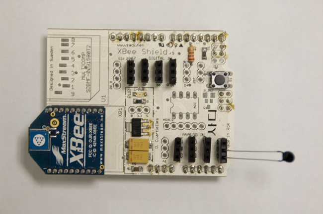
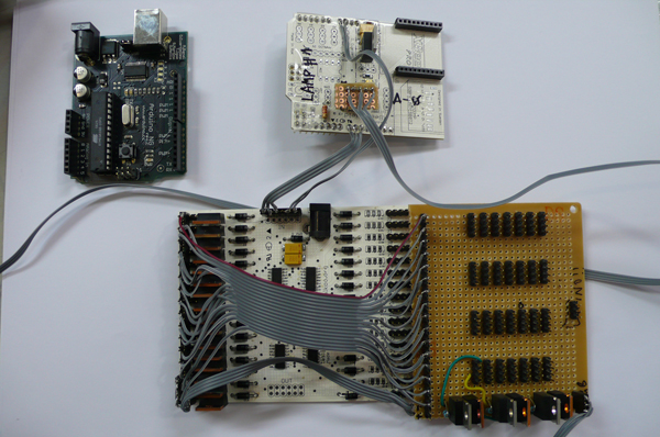
b) DIY Arduino board:
Make your own Arduino-compatible board. Using components available at
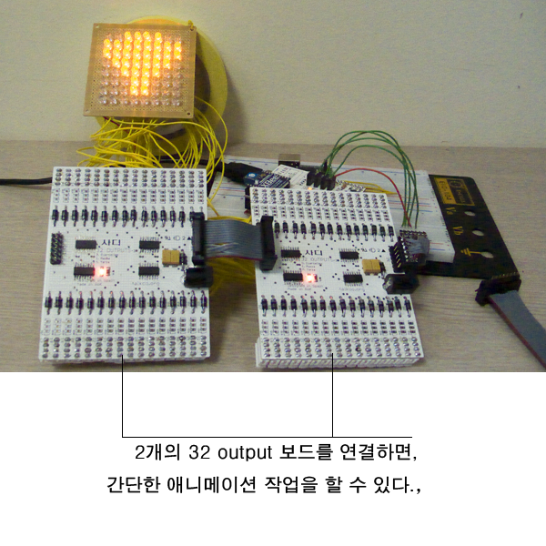
This first session will introduce the participants to the creation of a basic I/O platform. With it they can create all sort of physical computing devices, interactive artifacts, and electronic art installations.
a). 인트로 : 아듀이노 보드 설명
b) 아듀이노 보드 제작 : 일반 전기 부품을 가지고 직접 제작해 보는 시간. 다양한 애플리케이션과 연동이 가능한 보드 만들어 보기.
이 세션을 통해서 각자 가장 기본적인 I/O 보드를 만들어본다. 이를 통해 피지컬 컴퓨팅과 다양한 디바이스, 그리고 일렉트로닉 설치 작업에 관한 고민을 해 본다.
Day2: SOUND
a) short sound lecture: 8-bit sound as in Nintendo, Commodore, and Nokia ringtones
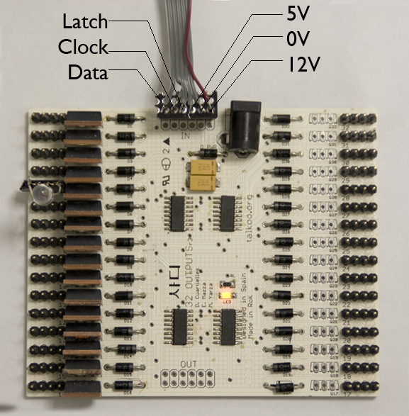
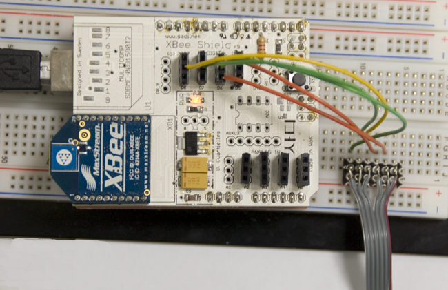
b) DIY Digital Music Instruments:
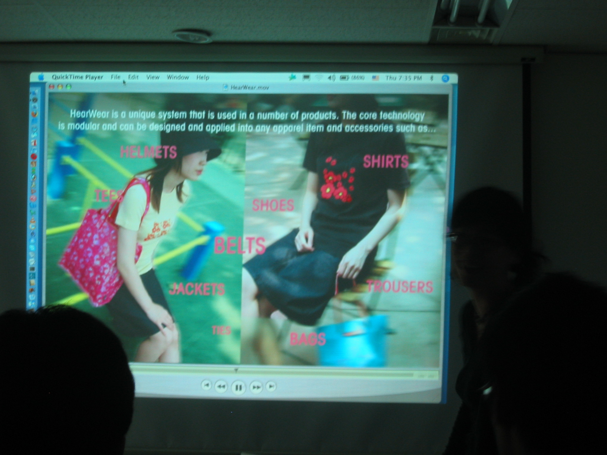
We will look into the creation of small music instruments that make use of our own homebrew Arduino board. Small interactive toys using buttons and knobs as interface will be produced.
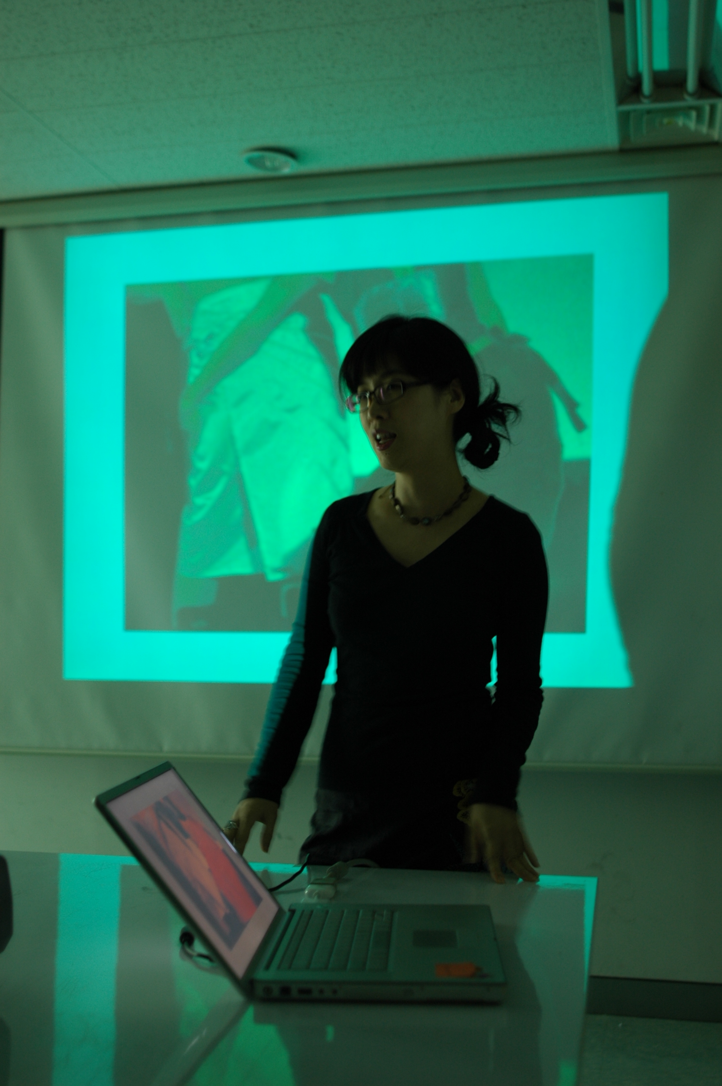
c) presentation: the participants will make small sound performances, as short as 2 minutes to explain their results
a). 사운드 : 노키아 링톤 (핸드폰 벨소리), 닌텐도 같은 8비트 소리에 관한 이해.
b) 직접 제작한 아듀이노 보드를 활용, 직접 악기를 제작해 본다. 버튼과 다양하고 쉬운 기기를 사용하여 인터엑티브 토이 구성..
c) 참가자는 직접 제작한 악기를 가지고 짦은 퍼포먼스를 진행해 본다.
------------------------------------------------------------------------------------------
[equipments]
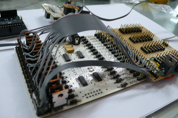
DIY Arduino Kit
: pcb, cable, connectors, sockets, microporcessors, sound speakers, power sockets, buttons
*** 본 워크샵 참여시 아트센터 나비에서 제공됩니다. Posted by nabi
--------------------------------------------------------------------------------
참가신청은 http://nabiworks.tistory.com/entry/D-I-Y-Arduino에서 신청 하실 수 있습니다.
출처: http://nabiworks.tistory.com/entry/D-I-Y-Arduino