

아두이노 microBee 확장보드 사용법
Technical References/Mobile 2007. 11. 7. 11:43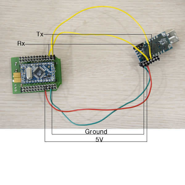
|
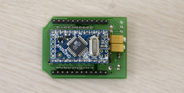
아두이노 microBee 확장보드 사용법Technical References/Mobile 2007. 11. 7. 11:43Arduino_mini_xbee 보드 연결방법Technical References/Mobile 2007. 11. 7. 11:30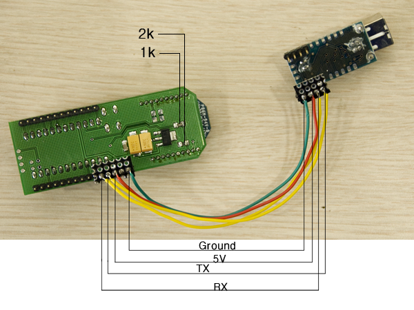 xbee 와 arduino 미니 보드를 사용하여 무선 통신 작업을 할 수 있는 보드가 만들어졌습니다. 이름은 miniBee 라고 명명되었고, 한 차례 수정을 거쳐 드디어 완성되었습니다. 아주 조그마한 크기로 만들어졌기때문에, 프로토 타입의 내부에 쉽게 삽입되어, 컴퓨터와 혹은 다른 Arduino Xbee 와 Serial 통신을 할 수 있습니다. 이 모듈을 이용하면, 다양한 아이디어를 실제로 프로토타입으로 구현해 볼 수 있을 겁니다. 예를 들어 몸에 부착시켜 놓고 몸의 반응을 떨어져 있는 컴퓨터와 통신을 하여 그래픽으로 처리한다던가 등의 작업이 가능하게 됩니다. 아직까지 베터리 문제가 있지만, 곧 해결될 수 있는 문제라고 생각합니다. 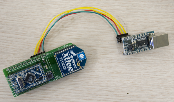 많은 분들의 다양한 아이디어를 기다립니다. 조금 더 쉽고 간단하게 지금까지와는 다른 Wireless 형태로 다양한 작업이 가능하리라 기대됩니다. DIY Arduino Digital Music InstrumentsNews/Events 2007. 10. 30. 01:12 Nabi_Academy 2007 단기 워크샵 DIY Arduino Digital Music Instruments [Facilitators] David Cuartielles with the help of DongHoo Kim, KeunGook Seok and Ahrum Kwon. [Date and time] 2007년 11월 5일(월) pm 5:00 ~ 9:00 class section 2007년 11월 6일(화) pm 1:00 ~ 4:00 catch up section Pm 5:00 ~ 9:00 class section [Location] 아트센터 나비(Art Center_nabi) 원형극장 [Participants] 최대 15명 (Max. 15 participants)
[Participants Requirements] No special requirements are needed, however it is preferred if the participants have some knowledge about sound production. We encourage the participants to bring their own laptops, if they have one. They should bring headphones. 참가자 필요 사항 : 사운드에 기초적인 관심과 배경 지식 환영. 랩탑 + 헤드폰 ------------------------------------------------------------------------------------------ [Workshop Objectives] - creation of open tools for artistic production - understanding open source culture - understanding basic concepts of low level sound/noise production -예술적 생산을 위한 오픈 툴 만들어 보기 -오픈소스 문화의 이해 -로우 레벨 사운드/ 노이즈 음악 제작의 이해 [Wokshop Outlines] Day 1: PROTOTYPING a) short introductory lecture: prototyping platforms, an overview of what exists and how it is used b) DIY Arduino board: a). 인트로 : 아듀이노 보드 설명 b) 아듀이노 보드 제작 : 일반 전기 부품을 가지고 직접 제작해 보는 시간. 다양한 애플리케이션과 연동이 가능한 보드 만들어 보기. 이 세션을 통해서 각자 가장 기본적인 I/O 보드를 만들어본다. 이를 통해 피지컬 컴퓨팅과 다양한 디바이스, 그리고 일렉트로닉 설치 작업에 관한 고민을 해 본다. Day2: SOUND a) short sound lecture: 8-bit sound as in Nintendo, Commodore, and Nokia ringtones b) DIY Digital Music Instruments: c) presentation: the participants will make small sound performances, as short as 2 minutes to explain their results a). 사운드 : 노키아 링톤 (핸드폰 벨소리), 닌텐도 같은 8비트 소리에 관한 이해. b) 직접 제작한 아듀이노 보드를 활용, 직접 악기를 제작해 본다. 버튼과 다양하고 쉬운 기기를 사용하여 인터엑티브 토이 구성.. c) 참가자는 직접 제작한 악기를 가지고 짦은 퍼포먼스를 진행해 본다. ------------------------------------------------------------------------------------------ [equipments] DIY Arduino Kit : pcb, cable, connectors, sockets, microporcessors, sound speakers, power sockets, buttons *** 본 워크샵 참여시 아트센터 나비에서 제공됩니다. Posted by nabi 단순한 애니메이션News/Events 2007. 10. 16. 18:12arduino를 활용한 간단한 애니메이션 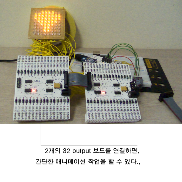 코드는 아래와 같으며, 기본적으로 3개의 이미지 파일을 연속해서 보여주는 코드이다. //****************************// //**********************************// // Name : shiftOutCode, Hello World // // Author : Carlyn Maw,Tom Igoe // // Date : 25 Oct, 2006 // // Version : 1.0 // // Notes : Code for using a 74HC595 Shift Register // // : to count from 0 to 255 // //**************************************************************** //Pin connected to ST_CP of 74HC595 int latchPin = 7; //Pin connected to SH_CP of 74HC595 int clockPin = 6; ////Pin connected to DS of 74HC595 int dataPin = 5; int numSymbols = 3; int icon[] = { B11111111, // I B11111111, B00011000, B00011000, B00011000, B00011000, B11111111, B11111111, B00111100, // Love B11111111, B11111111, B01111110, B00111100, B00011000, B00011000, B00000000, B11000011, // U B11000011, B11000011, B11000011, B11000011, B11000011, B01100110, B00111100 }; // FUNCTIONS void anim2() { for (int j = 0; j < numSymbols; j++) { digitalWrite(latchPin, LOW); shiftOut(dataPin, clockPin, MSBFIRST, icon[7+8*j]); shiftOut(dataPin, clockPin, MSBFIRST, icon[6+8*j]); shiftOut(dataPin, clockPin, MSBFIRST, icon[5+8*j]); shiftOut(dataPin, clockPin, MSBFIRST, icon[4+8*j]); shiftOut(dataPin, clockPin, MSBFIRST, icon[3+8*j]); shiftOut(dataPin, clockPin, MSBFIRST, icon[2+8*j]); shiftOut(dataPin, clockPin, MSBFIRST, icon[1+8*j]); shiftOut(dataPin, clockPin, MSBFIRST, icon[8*j]); digitalWrite(latchPin, HIGH); delay(1300); Serial.println(icon[2+8*j], BIN); Serial.println(icon[1+8*j], BIN); Serial.println(icon[8*j], BIN); Serial.println("**********"); } } // END FUNCTIONS void setup() { //set pins to output because they are addressed in the main loop pinMode(latchPin, OUTPUT); pinMode(clockPin, OUTPUT); pinMode(dataPin, OUTPUT); Serial.begin(9600); } void loop() { anim2(); delay(500); } 작동되면 다음과 같다. 아두이노 보드 지그비 확장 보드 사용법News/Events 2007. 10. 16. 15:10아누이노 지그비 보드는 지그비 통신을 사용가능하게 하는 보드이기도 하지만, 아두이노 초보 사용자에게 맞게 여러 가지 확장 기능을 제공하고 있다. 사디 인터랙션 디자인 랩에서 가장 아끼는 보드 디자인이다.
우선 아날로그 인풋을 쉽게 할 수 있도록 그룹핑시켜 놓았다. 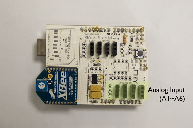 예를 들어 가변저항과 같은 경우, 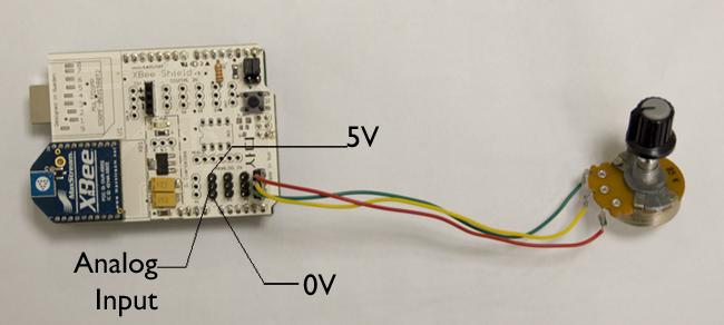 위 그림처럼 쉽게 사용할 수 있게 되어있다. 빛 센서나 열센서의 경우에는 다음과 같이 사용할 수 있게 되어있다. 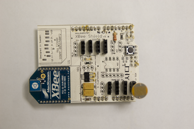 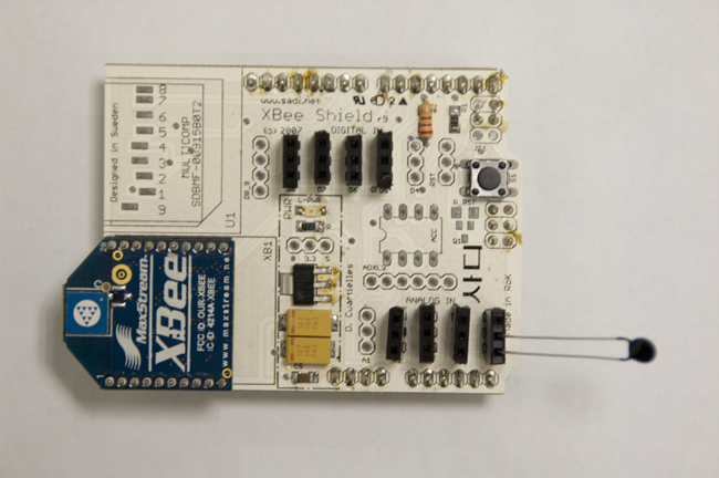 < 열 감지 센서의 경우도 마찬가지로 0 V 와 아나로그 인풋 포트만 사용하면 된다. > 아나로그 인풋 프로그램은 일반적으로 아래와 같이 테스트해볼 수 있다. /* * AnalogInput * by DojoDave <http://www.0j0.org> * * Turns on and off a light emitting diode(LED) connected to digital * pin 13. The amount of time the LED will be on and off depends on * the value obtained by analogRead(). In the easiest case we connect * a potentiometer to analog pin 2. * * http://www.arduino.cc/en/Tutorial/AnalogInput */ int potPin = 5; // select the input pin for the potentiometer int ledPin = 13; // select the pin for the LED int val = 0; // variable to store the value coming from the sensor void setup() { pinMode(ledPin, OUTPUT); // declare the ledPin as an OUTPUT Serial.begin(9600); } void loop() { val = analogRead(potPin); // read the value from the sensor digitalWrite(ledPin, HIGH); // turn the ledPin on delay(val); // stop the program for some time digitalWrite(ledPin, LOW); // turn the ledPin off delay(val); // stop the program for some time Serial.println(val, DEC); } 32개의 아웃풋을 지원하는 보드 사용법 소개News/Events 2007. 10. 16. 14:17아두이노 보드를 사용하여 32개 혹은 64개의 아웃풋을 제어할 수 있는 확장보드로, 연결방법은 다음과 같습니다. 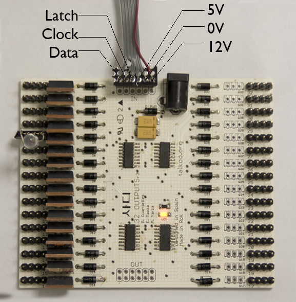 일단 아누이노의 3개의 핀으로 제어가 가능한 형태로 제작되었고, 샘플 프로그램은 아래와 같다. //**************************** // Name : shiftOutCode, Hello World // // Author : Carlyn Maw,Tom Igoe // // Date : 25 Oct, 2006 // // Version : 1.0 // // Notes : Code for using a 74HC595 Shift Register // // : to count from 0 to 255 // //**************************** //Pin connected to ST_CP of 74HC595 int latchPin = 10; //Pin connected to SH_CP of 74HC595 int clockPin = 9; ////Pin connected to DS of 74HC595 int dataPin = 8; //variable to store the first byte of data int light0_7 = 0; int light8_15 = 0; // FUNCTIONS void pinON(int pinNumber) { if (pinNumber <= 8) light0_7 |= 1<<(pinNumber-1); else light8_15 |= 1<<(pinNumber-9); digitalWrite(latchPin, LOW); shiftOut(dataPin, clockPin, MSBFIRST, light8_15); shiftOut(dataPin, clockPin, MSBFIRST, light0_7); digitalWrite(latchPin, HIGH); } void pinOFF(int pinNumber) { if (pinNumber <= 8) light0_7 &= ~(1<<(pinNumber-1)); else light8_15 &= ~(1<<(pinNumber-9)); digitalWrite(latchPin, LOW); shiftOut(dataPin, clockPin, MSBFIRST, light8_15); shiftOut(dataPin, clockPin, MSBFIRST, light0_7); digitalWrite(latchPin, HIGH); } // END FUNCTIONS void setup() { //set pins to output because they are addressed in the main loop pinMode(latchPin, OUTPUT); pinMode(clockPin, OUTPUT); pinMode(dataPin, OUTPUT); pinON(5); pinON(8); } void loop() { pinON(3); delay(1000); pinOFF(3); delay(1000); } 위 프로그램이 하는 일은 5번 핀과 8번 핀은 항상 켜둔채, 3번 핀을 깜박거리게 하는 프로그램이다. 아두이노 확장 보드와 연결하면 다음과 같은 모습이다. 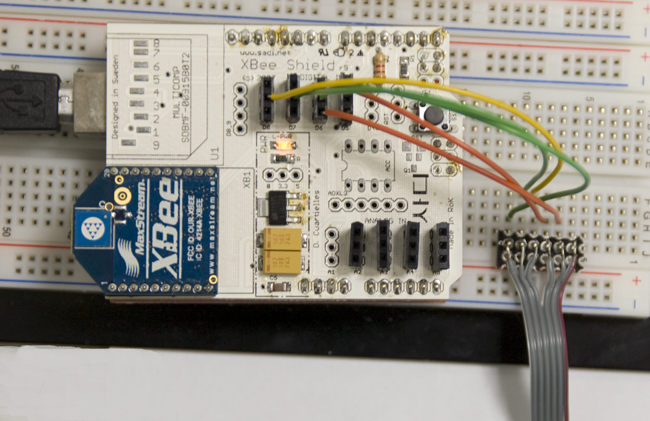 김영희's 세미나 WORKNews/Guest Speakers 2007. 10. 9. 16:3010월 4일 Sadi Interaction Lab에서 김영희씨는 뉴욕에서의 작업과 최근 활동들을 소개하고
랩 스탭들 및 외부 참여자들과 함께 워크샵을 가졌습니다. 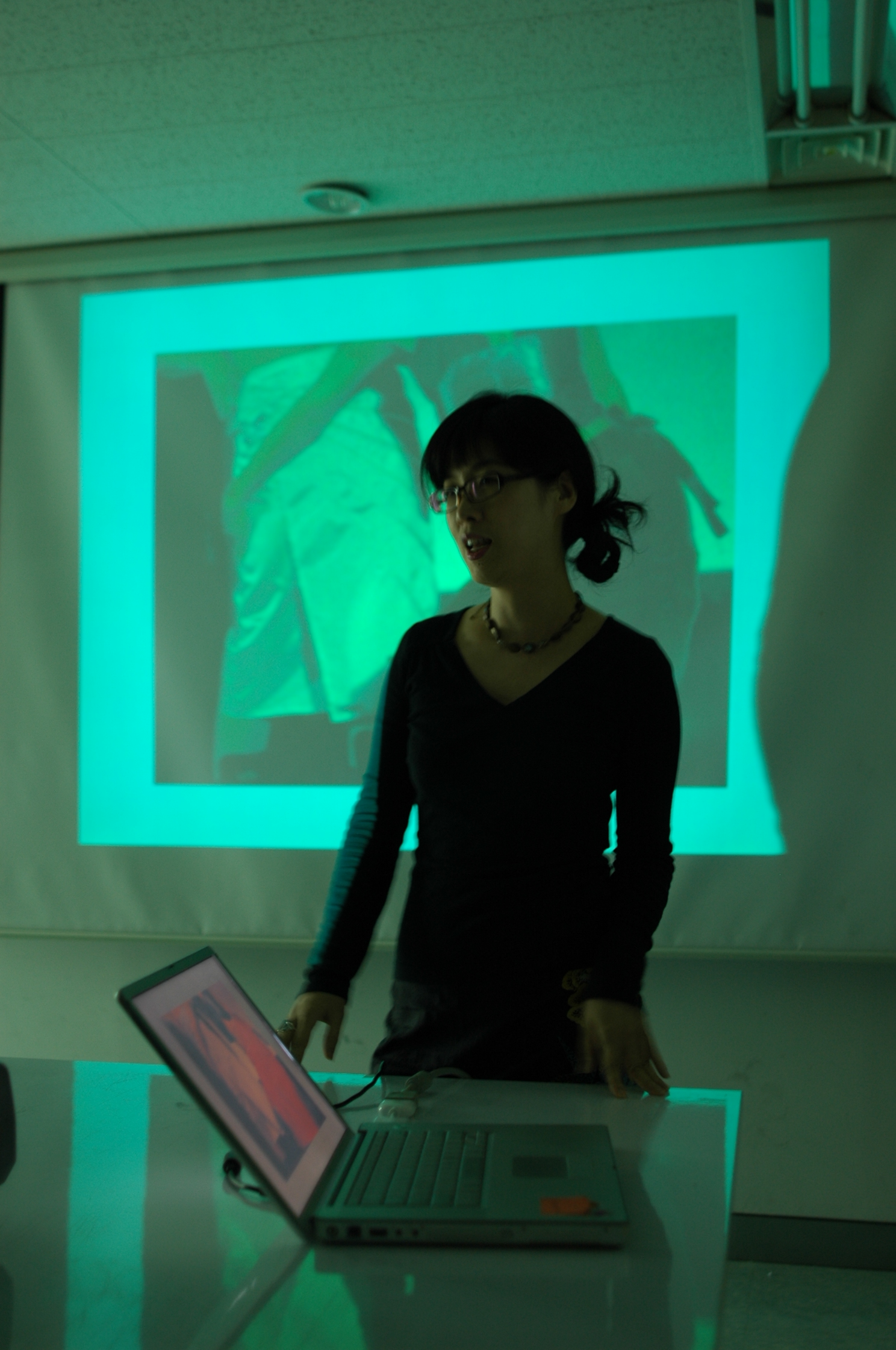 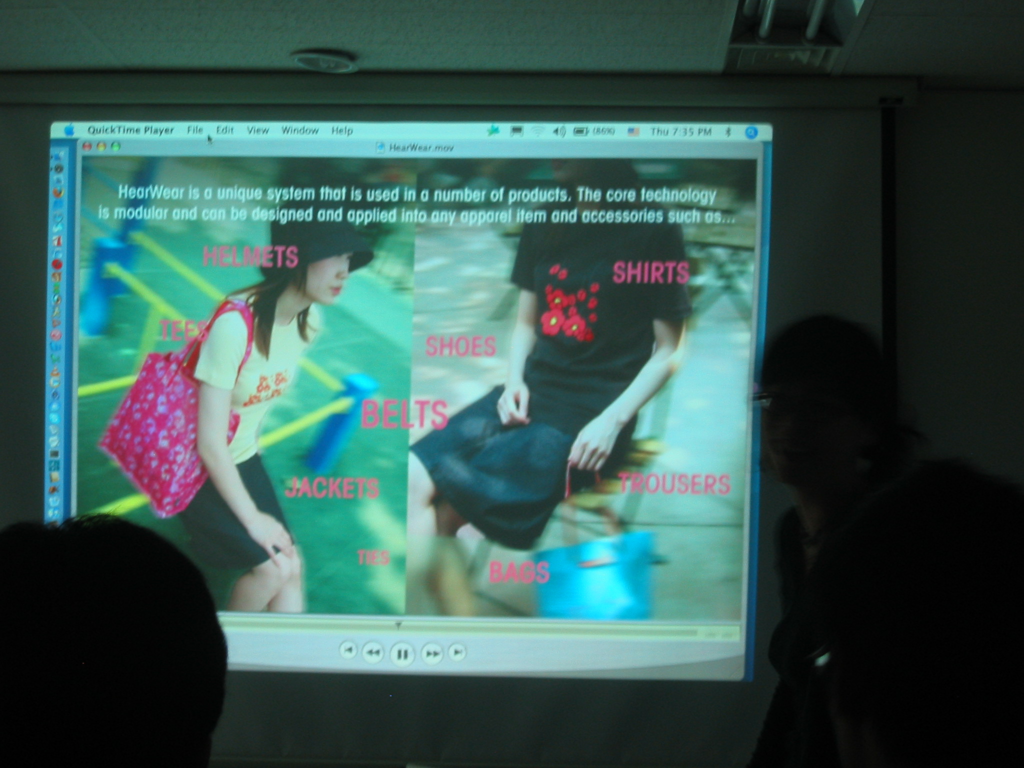 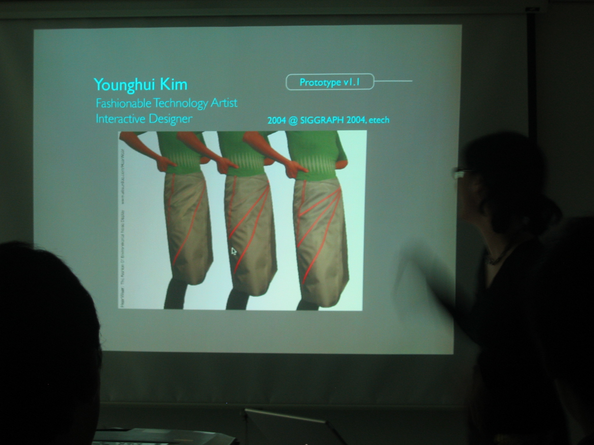 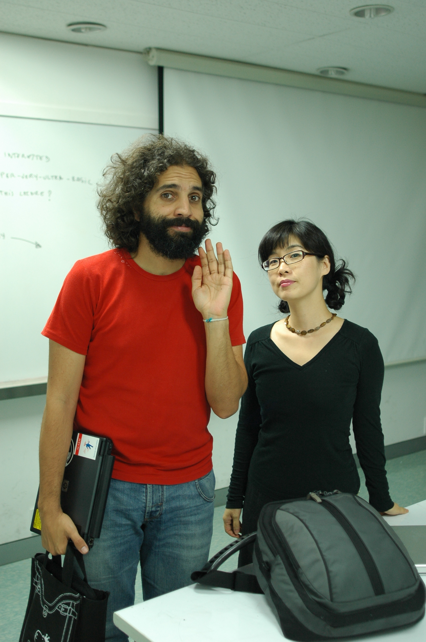 광주 비엔날레에 참여하는 작품제작 지원News/Events 2007. 10. 4. 00:54김동후, 석근국, 권아름 학생이 인터랙티브 조명으로 광주비엔날레에 작품을 전시합니다. 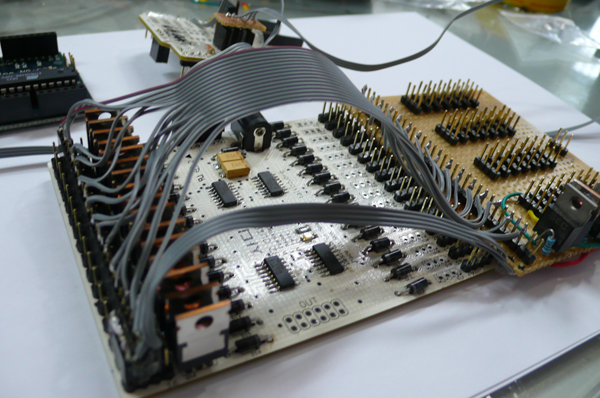 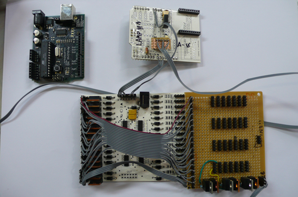 LEDs test for changing the colour properly with wireless sever 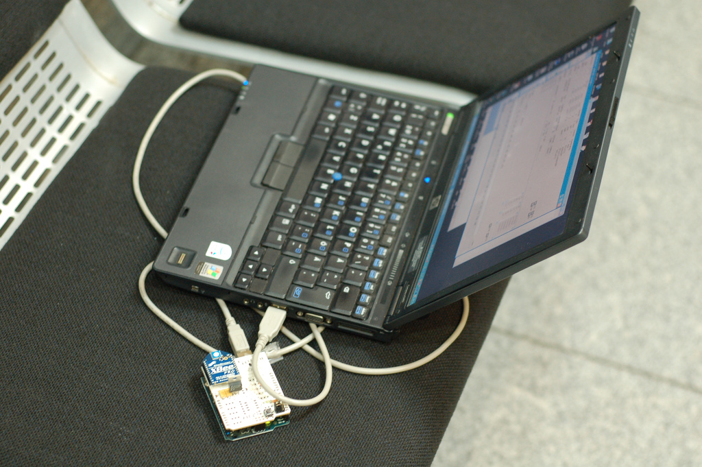
wireless server 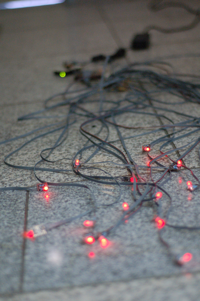 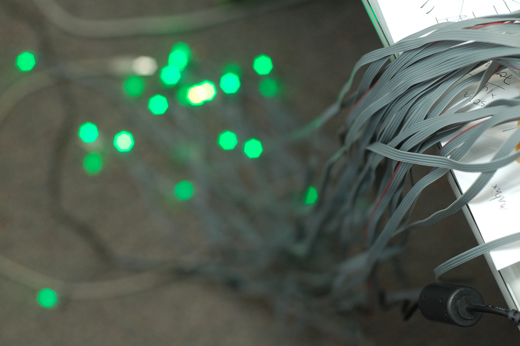
change the LEDs colour (from red to green) SADI Arduino Lignt & Sound ProjectTechnical References/Sound 2007. 10. 1. 17:19Xbee 보드를 이용한 사운드 및 라이트 콘트롤
void loop() { delay(100); } int isHigh = 0; void setup() { // set the data rate for the SoftwareSerial port void loop() { 아두이노 (Arduino) 확장 보드News/Events 2007. 9. 28. 13:57Sadi Interaction Design Lab에서는 아두이노 사용자를 위한 6개의 확장 보드를 개발하였습니다. 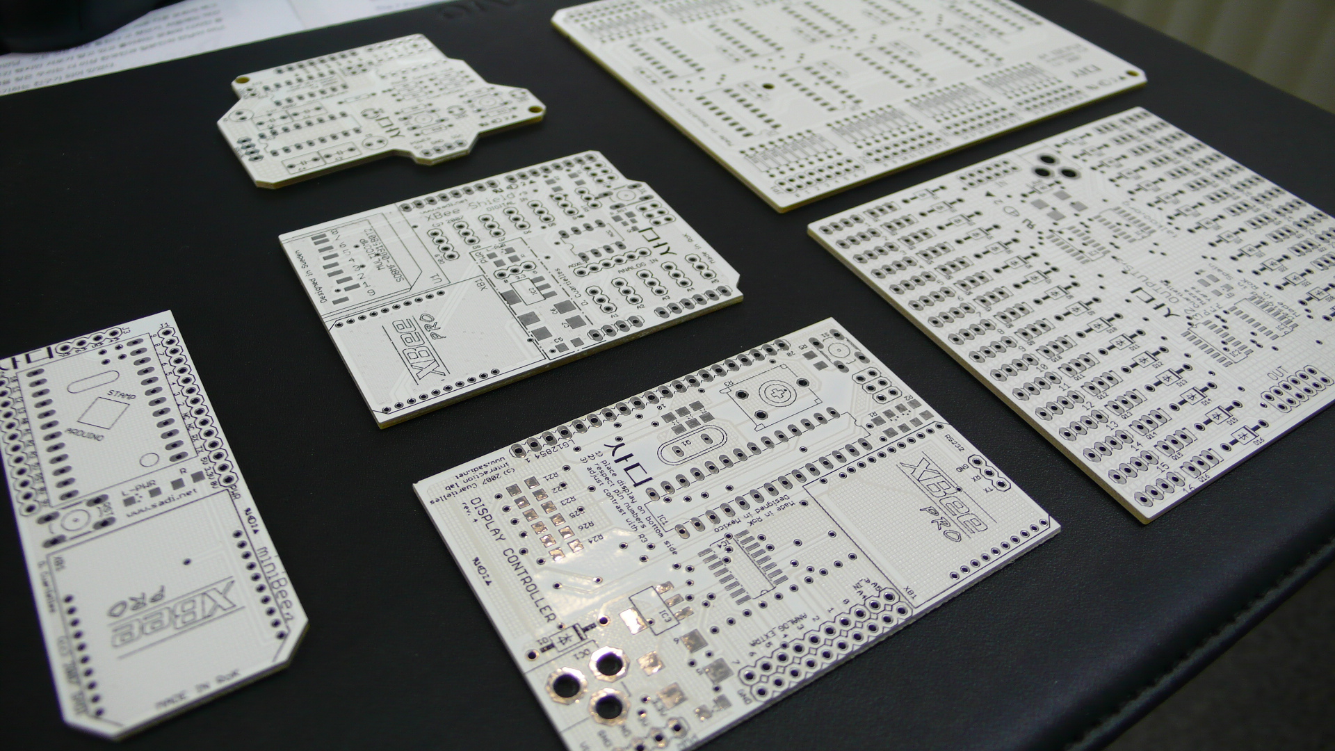 6개의 확장보드를 사용하여 할 수 있는 일은 다음과 같습니다. 1. 32 output - 이 많은 양의 output을 한 Arduino 보드로 컨트롤 할 수 있도록 디자인되어 있다. 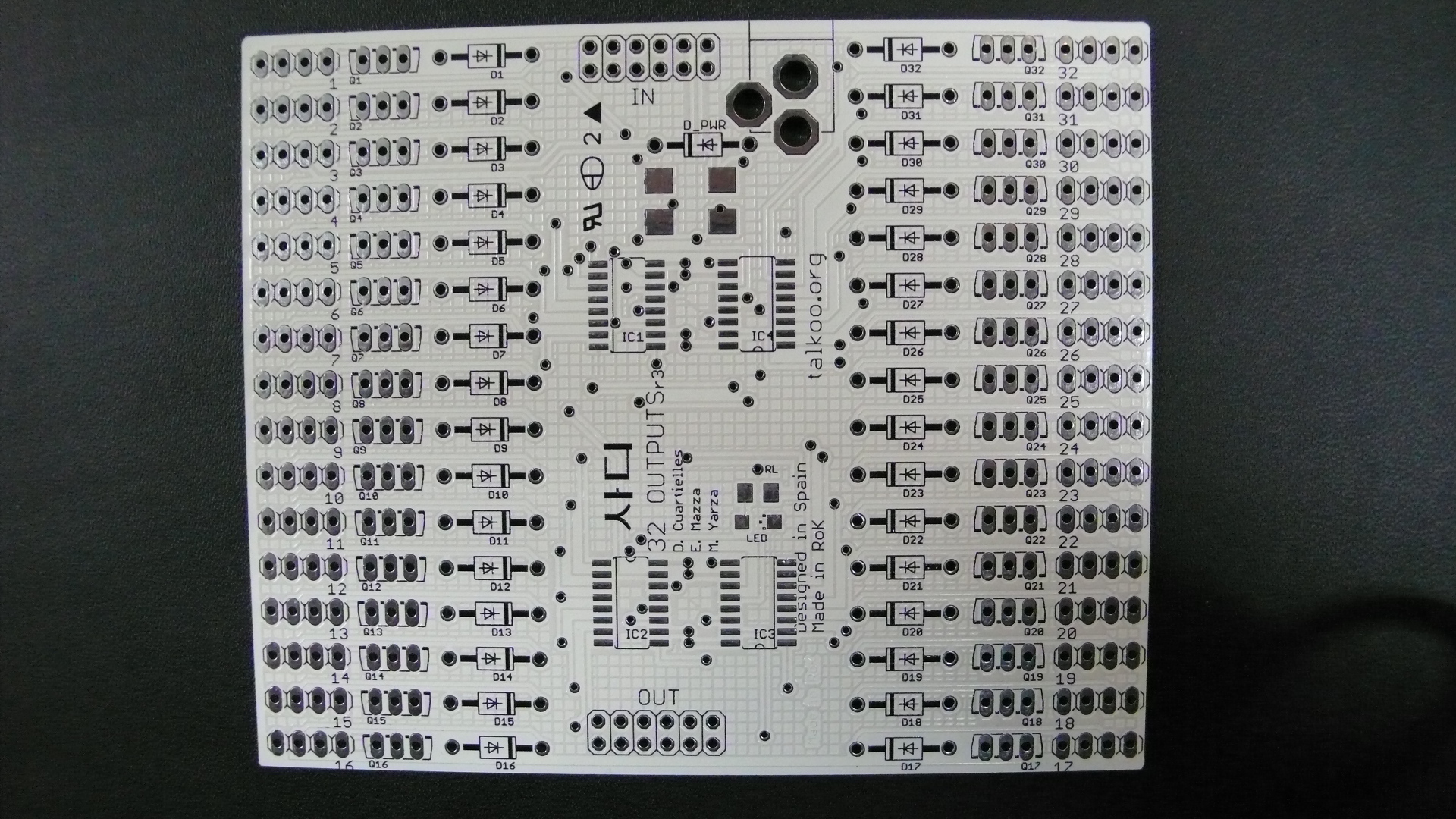 2. 64 input - 이 보드는 64개의 센서들을 동시에 읽어낼 수 있도록 디자인되어 있다. 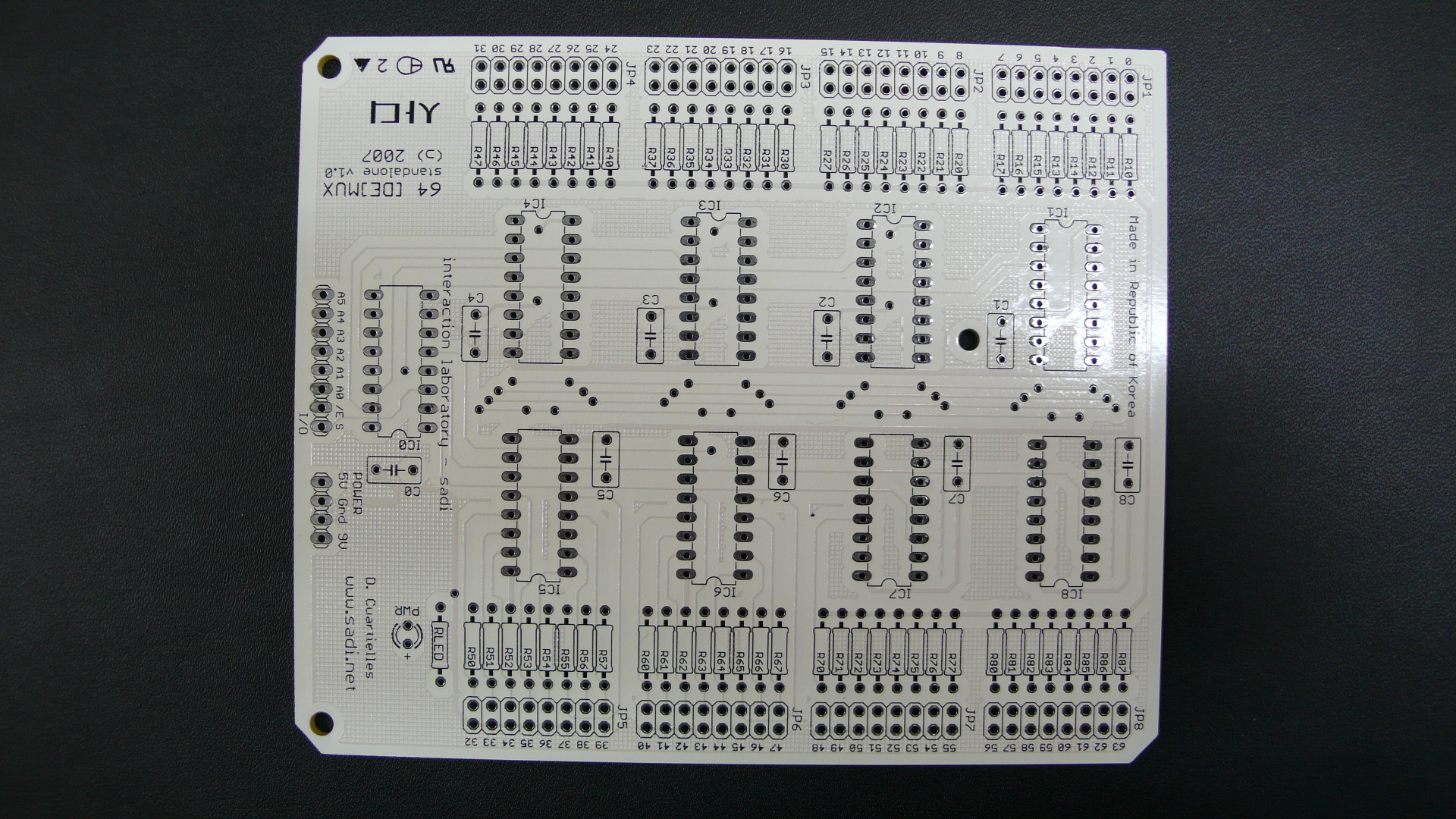 3. motor shield - 모터를 컨트롤하기 편리하게 디자인되어 있다. 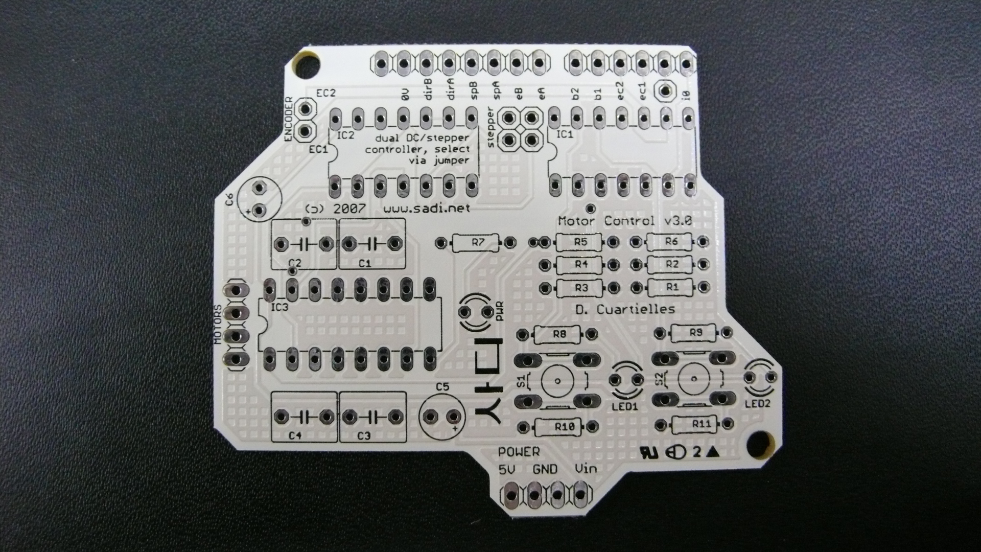 4. Arduino mini with Xbee - Xbee와 Arduino mini를 결합하여 작은 사이즈의 무선 통신 모듈을 개발 할 수 있도록 되어있다. 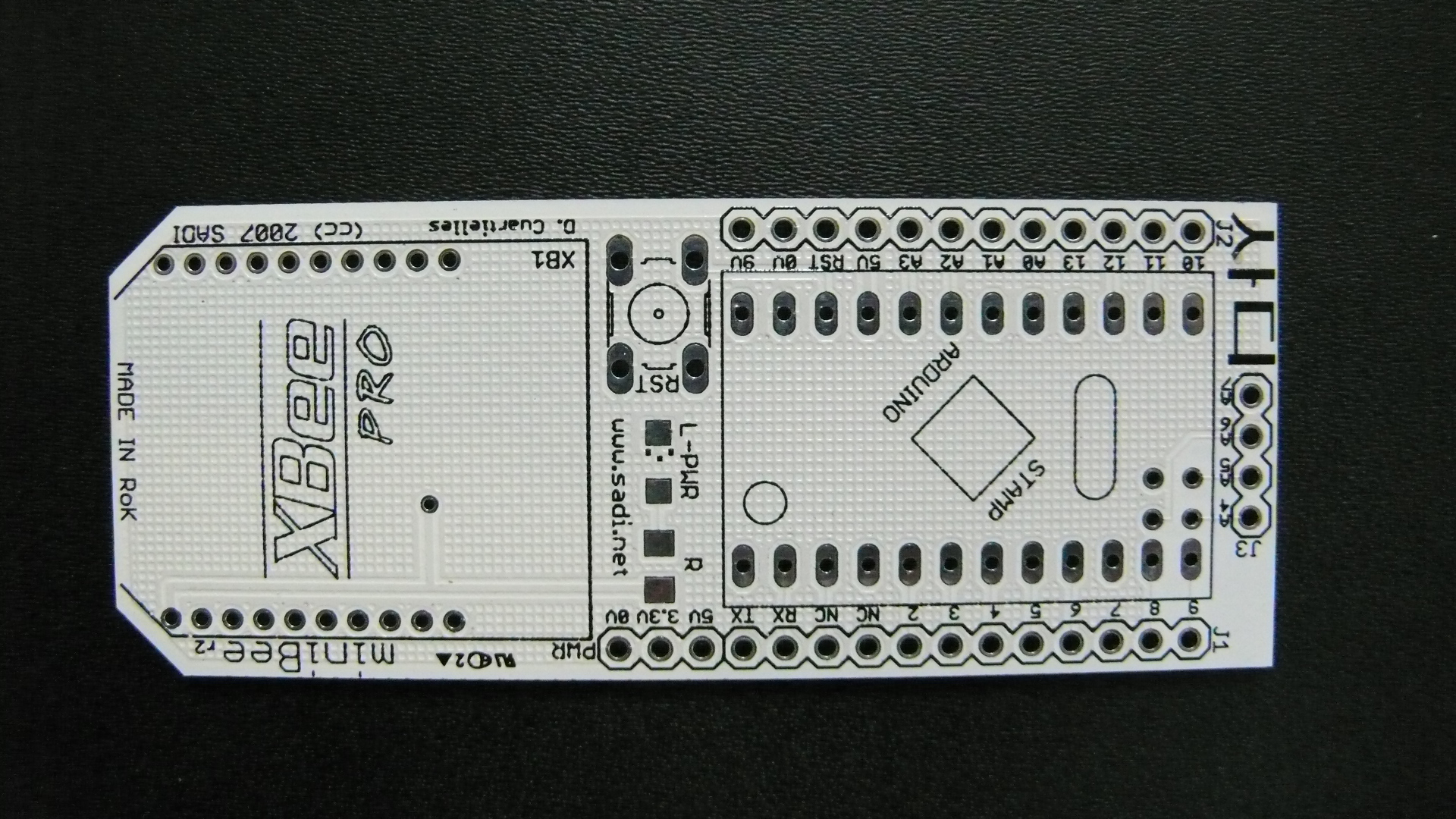 5. MultiLCD circuit - LCD display를 쉽게 사용할 수 있도록 디자인되어 있다. 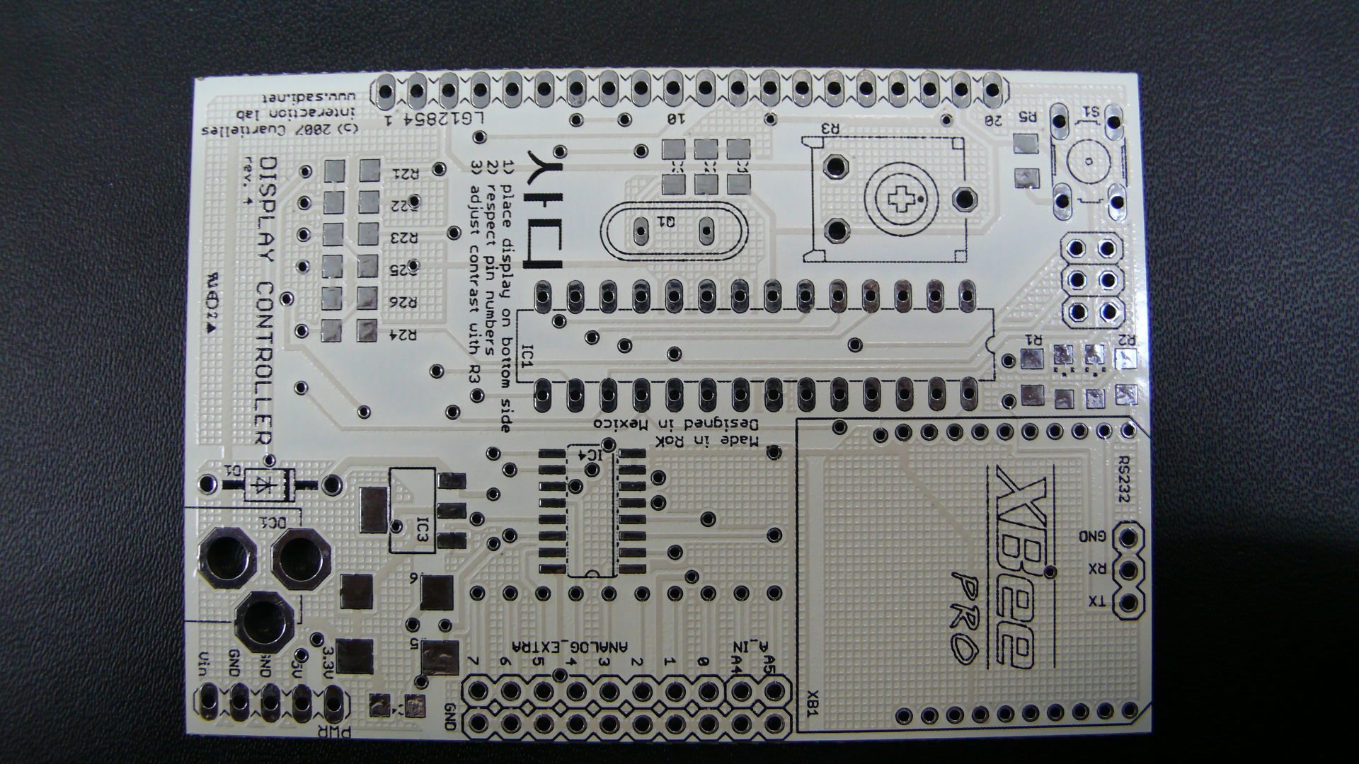 6. Xbee shield - Xbee를 이용하여 근거리 무선 통신을 할 수 있도록 디자인되어있다. 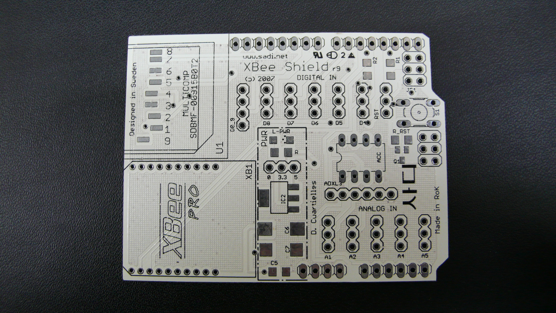 지금 개발중인 보드는 곧 Sadi를 통하여 일반인에게 공개되고, 배포될 예정입니다. |