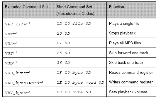
수업시간에 사용된 MP3 Player Module은 대만 회사인 Future Technology Devices International 의 VMusic1 MP3 Test Module 이다. 본 모듈의 사용명령어는 다음의 사이트에서 찾을 수 있다. http://www.vinculum.com/
Code example to play from MP3 players
There exist a whole range of MP3 players that can be controlled from the serial port in a microcontroller. In this example we will use a new type of player that can play files stored in a USB-flash disk.
//MP3 control
int skipPin = 12;
int playPausePin = 13;
int val = 1;
int isPlaying = 0;
int isBeginning = 1;
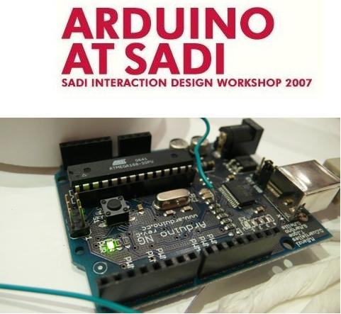
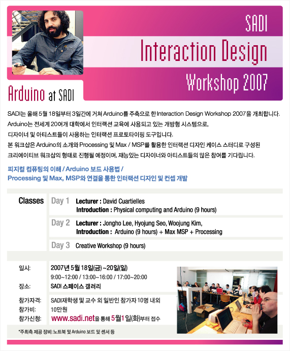
Sadi 인터랙션 디자인 연구소는 올해 2007년 5월 18일 부터 3일간에 거쳐 Arduino를 주축으로 한 Interaction Design Workshop 2007을 개최하였습니다. 사디학생을 포함하여 총 50명이 참여한 본 워크샵은 다양한 결과물을 만들어내며 성공리에 진행되었습니다.
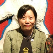
안녕하세요? 강슬기입니다. 현재 저는 바이널 미디어아트연구소 아트디렉터로 재직중이고 atoyfactory에 멤버로 활동하고 있습니다.. 사실 전 그래픽디자인으로 시작을 했지만 좀 더 폭넓은 디자인의 영역을 공부하고자 외도중입니다.
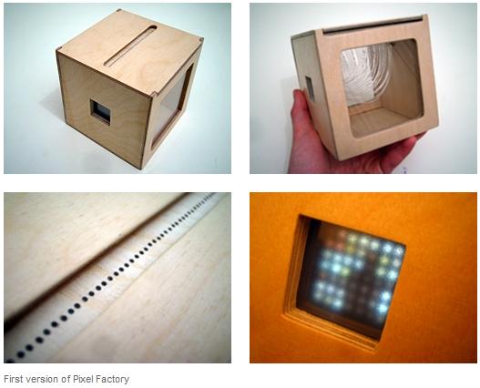
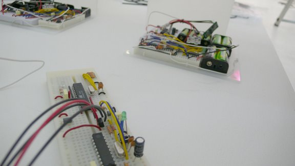
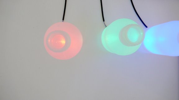
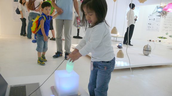
SADI에서 이렇게 좋은 자리를 어렵게 마련해주셨는데 걱정이네요 잘 할 수 있을지... ^^ 오늘은 무거운 주제보단 제가 생각하고 추구하고자하는 디자인을 제가 했던 작업 또는 프로토타입과 함께 간단하게 소개하고 싶습니다. 오늘 보여드릴 작업은 Pixel factory와 최근 작업인 Mixist를 가지고 얘기하려고 합니다.
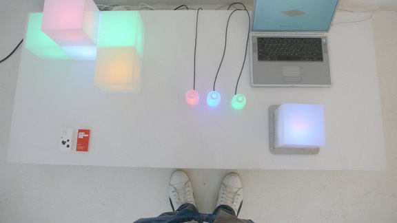
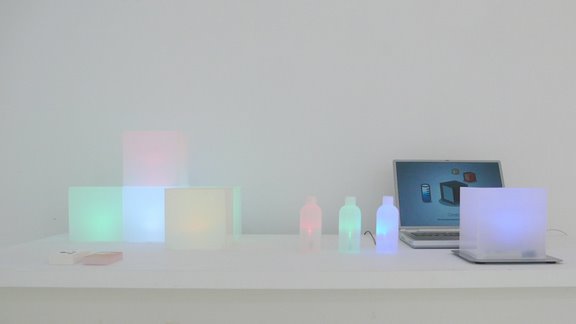
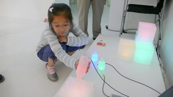
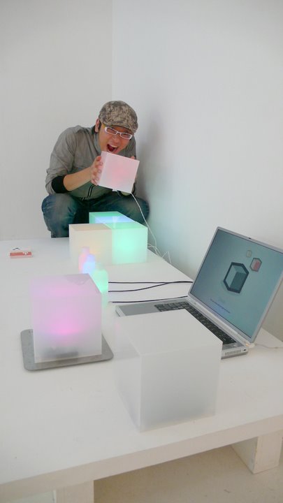
The main topic of the day is the use of light as an expressive way of interaction. As examples of different light projects, we have seen a bunch of movies taken from different projects existing on the internet.
[Tabletalk by Eriksson, Sjunnesson, Gedin et al.]
[butterfly a German table lamp]
['Borg3D' an interesting 3D LED lamp]
[a NONO on the design business]
['DaTable' from The Netherlands]
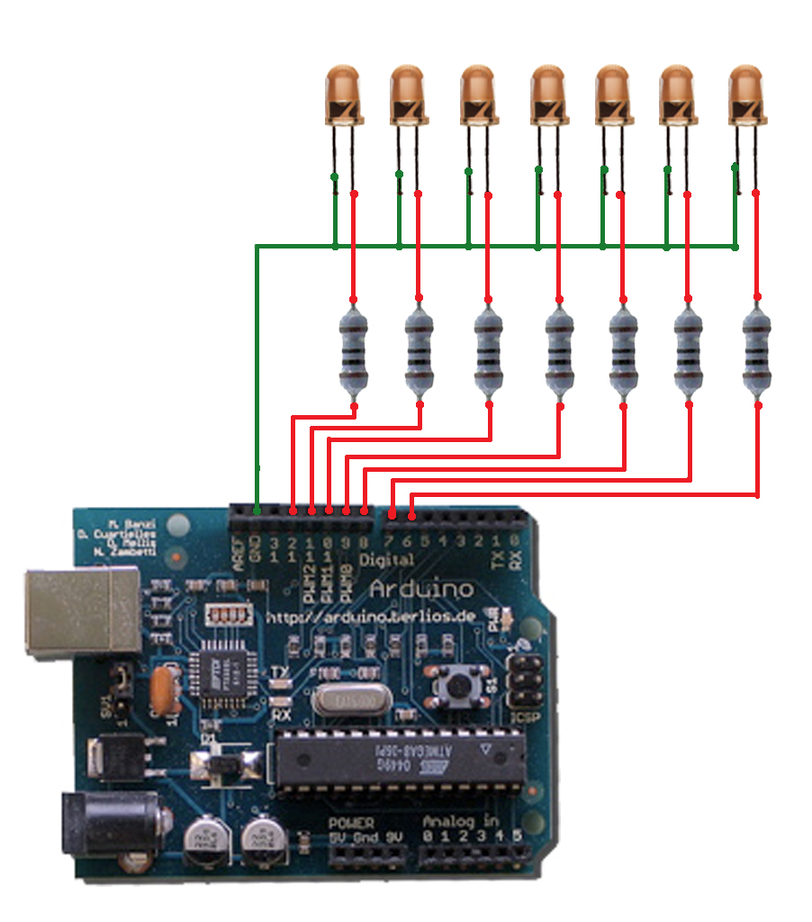
Code example for a P.O.V. device
An array of LEDs changing their values in time at a high speed, can simulate to be many more thanks to the P.O.V. cognitive effect.
int ledPin[7] = {6,7,8,9,10,11,12,}; int matrix[7][12] = {0,1,1,1,0,0,0,1,0,0,0,1, 1,0,0,0,1,0,0,1,0,0,1,0, 1,0,0,0,1,0,0,1,0,1,0,0, 1,0,0,0,1,0,0,1,1,1,0,0, 1,0,0,0,1,0,0,1,0,0,1,0, 1,0,0,0,1,0,0,1,0,0,0,1, 0,1,1,1,0,0,0,1,0,0,0,1 }; int i,j;
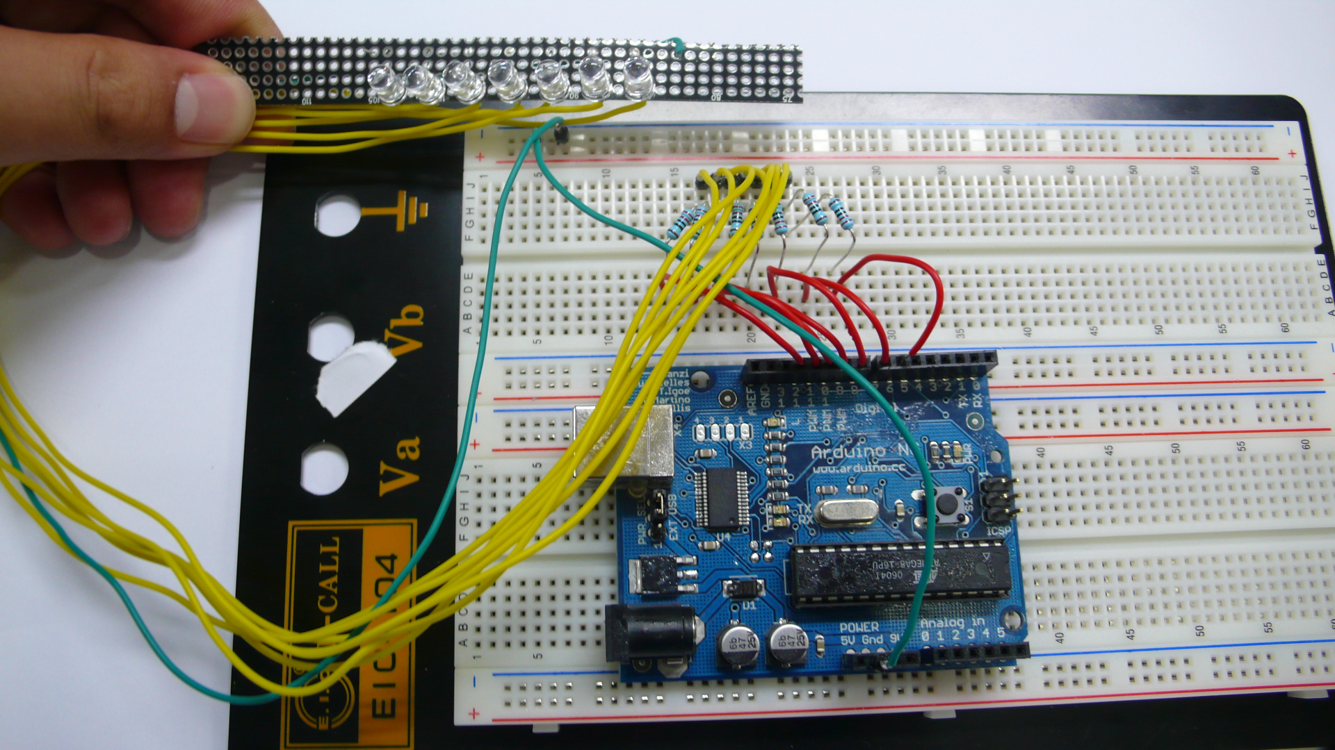
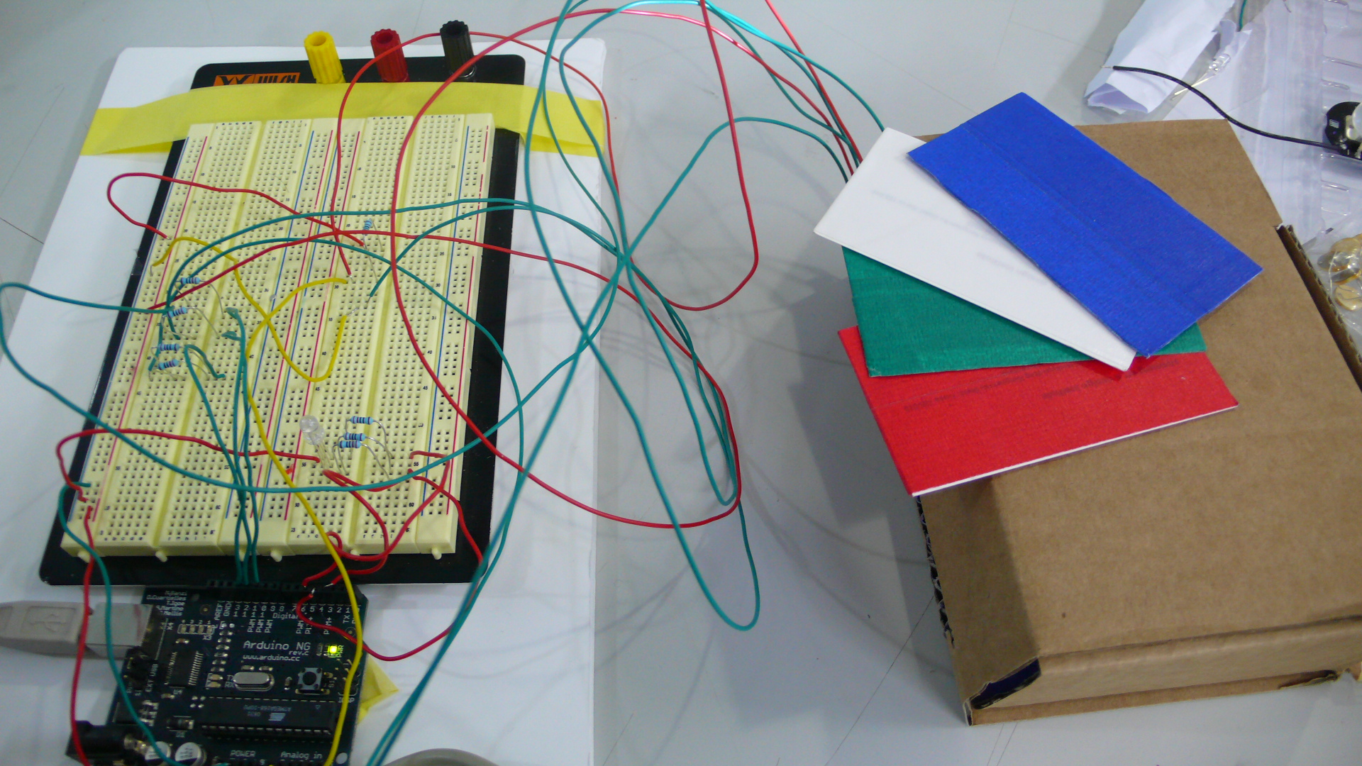
12번/13번 핀에 위와 동일한 구조의 회로를 하나 더 만들어서 연결해야한다. (두개의 LED를 연동 시키기 위해서)
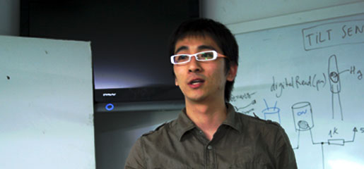
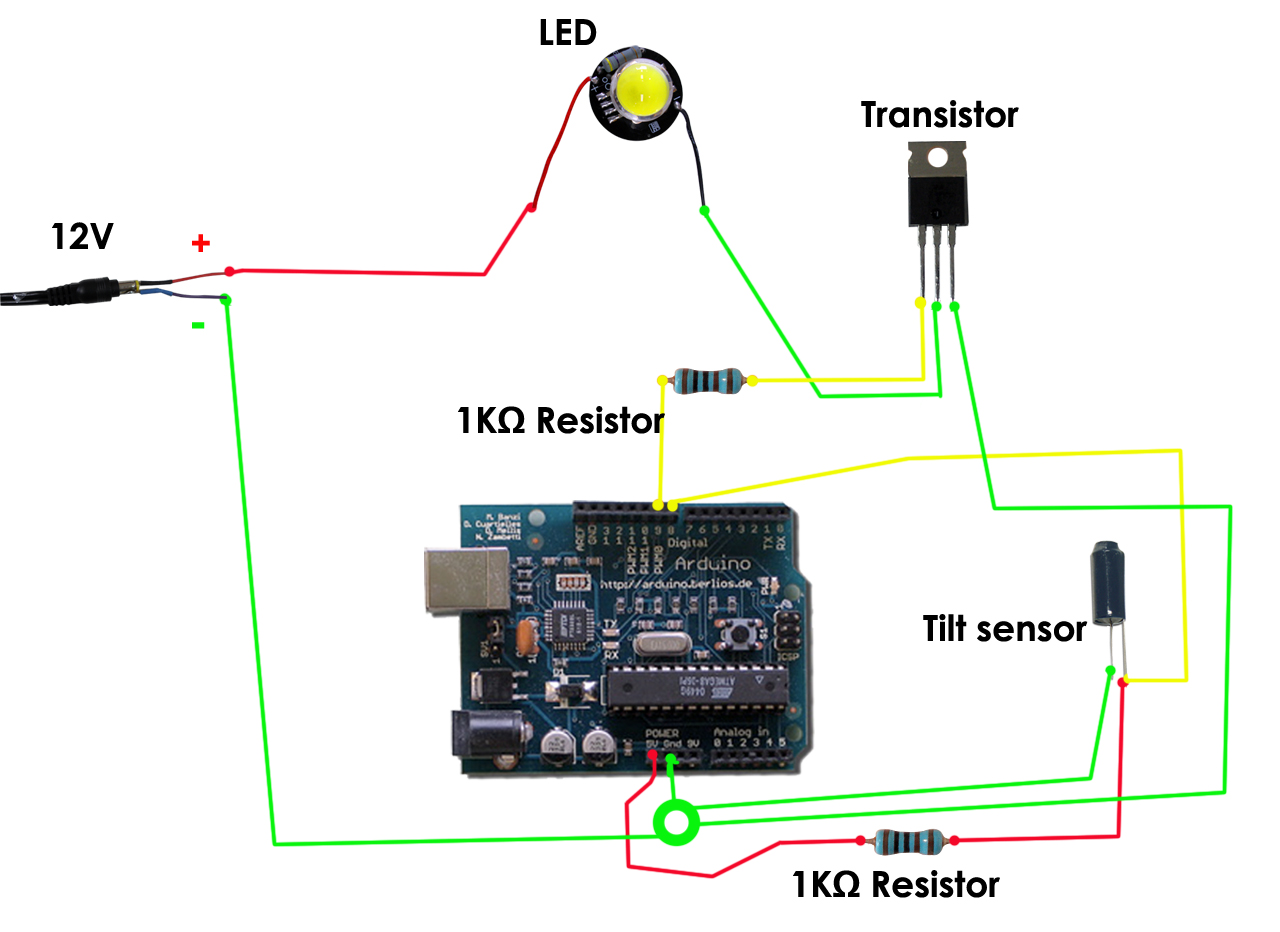
틸트 센서의 기울기에 따라 전구의 불빛에 변화를 줄 수 있도록 만들었다. 틸트 센서에서 기울기 값을 아듀이노 보드로 보내고 아듀이노 보드는 트랜지스터에 그 시그널을 보낸다. 트랜지스터는 그 값에 따라 LED를 on/off 시킨다. (트랜지스터는 스위치와 같은 역할을 한다)
With the use of Tilt sensors and powerful LEDs we can simulate a transfer of light between two different devices. They can be used to illuminate spaces, location markers, energy indicators ...
int tiltInA = 12; // Tilt 1 connected to digital pin 9 int tiltInB = 13; // Tilt 2 connected to digital pin 9
int pwmOutA = 9; // MOSFET connected to analog pin 3 int pwmOutB = 10; // MOSFET connected to analog pin 3
int amountOfA = 255; // variable to store the read value int amountOfB = 0;
if(amountOfB < 0){ amountOfB = 0; amountOfA = 255; //don't need to check A, because A + B = always 255 } }
//analogWrite(ledPin, val / 4); // analogRead values go from 0 to 1023, analogWrite values from 0 to 255 analogWrite(pwmOutA, amountOfA); Serial.println(amountOfA, DEC); delay(5); analogWrite(pwmOutB, amountOfB); Serial.println(amountOfB, DEC); delay(5);
}
Code example for a color sensor
Sensing colors is just about measuring the amount of each component of light. Let's see how accurate we can become in reading colors from different objects and expressing them through RGB LEDs.
// default change values as in the lab
// recalibrate for you own system
//                      R    G    B    W
int matrixRGB[3][4] = {680, 643, 578, 375,
                       759, 631, 720, 360,
                       254, 591, 603, 210 };
// safety margin
int sM = 30;

// LED pin out
int ledPinIn_R = 12;
int ledPinIn_B = 11;
int ledPinIn_G = 10;

int ledPinOut_R = 5;
int ledPinOut_B = 4;
int ledPinOut_G = 3;

// analog sensor (LDR)
int analogPin = 0;
int val_R = 0;
int val_G = 0;
int val_B = 0;

// start up calibration
int cal_R = 0;
int cal_G = 0;
int cal_B = 0;

void lightBLUE() {
  digitalWrite(ledPinOut_R, HIGH);
  digitalWrite(ledPinOut_G, HIGH);
  digitalWrite(ledPinOut_B, LOW);
  Serial.println("it is BLUE");
}

void lightRED() {
  digitalWrite(ledPinOut_R, LOW);
  digitalWrite(ledPinOut_G, HIGH);
  digitalWrite(ledPinOut_B, HIGH);
  Serial.println("it is RED");
}

void lightGREEN() {
  digitalWrite(ledPinOut_R, HIGH);
  digitalWrite(ledPinOut_G, LOW);
  digitalWrite(ledPinOut_B, HIGH);
  Serial.println("it is GREEN");
}

void lightWHITE() {
  digitalWrite(ledPinOut_R, LOW);
  digitalWrite(ledPinOut_G, LOW);
  digitalWrite(ledPinOut_B, LOW);
  Serial.println("it is WHITE");
}

void noLight() {
  digitalWrite(ledPinOut_R, HIGH);
  digitalWrite(ledPinOut_G, HIGH);
  digitalWrite(ledPinOut_B, HIGH);
}

void demoLight() {
  for (int i = 0; i < 3; i++) {
  lightBLUE();
  delay(100);
  lightGREEN();
  delay(100);
  lightRED();
  delay(100);
  lightWHITE();
  delay(100);
  }
  noLight();
}

void calibrate() {
  for(int c = 0; c < 10; c++) {
  //RED
  digitalWrite(ledPinIn_R, LOW);
  digitalWrite(ledPinIn_G, HIGH);
  digitalWrite(ledPinIn_B, HIGH);
  delay(100);
  if (c > 0) {
  cal_R += analogRead(analogPin);
  cal_R /= 2;
  } else {
  cal_R = analogRead(analogPin);
  }
  delay(50);

  //GREEN
  digitalWrite(ledPinIn_R, HIGH);
  digitalWrite(ledPinIn_G, LOW);
  digitalWrite(ledPinIn_B, HIGH);
  delay(100);
  if (c > 0) {
  cal_G += analogRead(analogPin);
  cal_G /= 2;
  } else {
  cal_G = analogRead(analogPin);
  }
  delay(50);

  //BLUE
  digitalWrite(ledPinIn_R, HIGH);
  digitalWrite(ledPinIn_G, HIGH);
  digitalWrite(ledPinIn_B, LOW);
  delay(100);
  if (c > 0) {
  cal_B += analogRead(analogPin);
  cal_B /= 2;
  } else {
  cal_B = analogRead(analogPin);
  }
  delay(50);
  }
}

void setup(){
  pinMode(ledPinIn_R, OUTPUT);
  pinMode(ledPinIn_G, OUTPUT);
  pinMode(ledPinIn_B, OUTPUT);

  pinMode(ledPinOut_R, OUTPUT);
  pinMode(ledPinOut_G, OUTPUT);
  pinMode(ledPinOut_B, OUTPUT);

  Serial.begin(9600);

  // calibrate the sensors and print out the values
  demoLight();
  calibrate();
  Serial.println("************************");
  Serial.print("RED calibration: ");
  Serial.println(cal_R, DEC);
  Serial.print("GREEN calibration: ");
  Serial.println(cal_G, DEC);
  Serial.print("BLUE calibration: ");
  Serial.println(cal_B, DEC);
  Serial.println("************************");

}

void loop(){

  //RED
  digitalWrite(ledPinIn_R, LOW);
  digitalWrite(ledPinIn_G, HIGH);
  digitalWrite(ledPinIn_B, HIGH);
  delay(100);
  val_R = analogRead(analogPin);
  //Serial.print("RED ");
  //Serial.println(val_R, DEC);
  delay(100);

  //GREEN
  digitalWrite(ledPinIn_R, HIGH);
  digitalWrite(ledPinIn_G, LOW);
  digitalWrite(ledPinIn_B, HIGH);
  delay(100);
  val_G = analogRead(analogPin);
  //Serial.print("GREEN ");
  //Serial.println(val_G, DEC);
  delay(100);

  //BLUE
  digitalWrite(ledPinIn_R, HIGH);
  digitalWrite(ledPinIn_G, HIGH);
  digitalWrite(ledPinIn_B, LOW);
  delay(100);
  val_B = analogRead(analogPin);
  //Serial.print("BLUE ");
  //Serial.println(val_B, DEC);
  delay(100);

    if (val_R < matrixRGB[0][3] + sM && val_G < matrixRGB[1][3] +
                                sM && val_B < matrixRGB[2][3] + sM)
          lightWHITE();
    else if (val_R < matrixRGB[0][2] + sM && val_G < matrixRGB[1][2] +
                                sM && val_B < matrixRGB[2][2] + sM)
          lightBLUE();
    else if (val_R < matrixRGB[0][1] + sM && val_G < matrixRGB[1][1] +
                                 sM && val_B < matrixRGB[2][1] + sM)
          lightGREEN();
    else if (val_R < matrixRGB[0][0] + sM && val_G < matrixRGB[1][0] +
                                 sM && val_B < matrixRGB[2][0] + sM)
          lightRED();
    else
          noLight();

  delay(200);

}
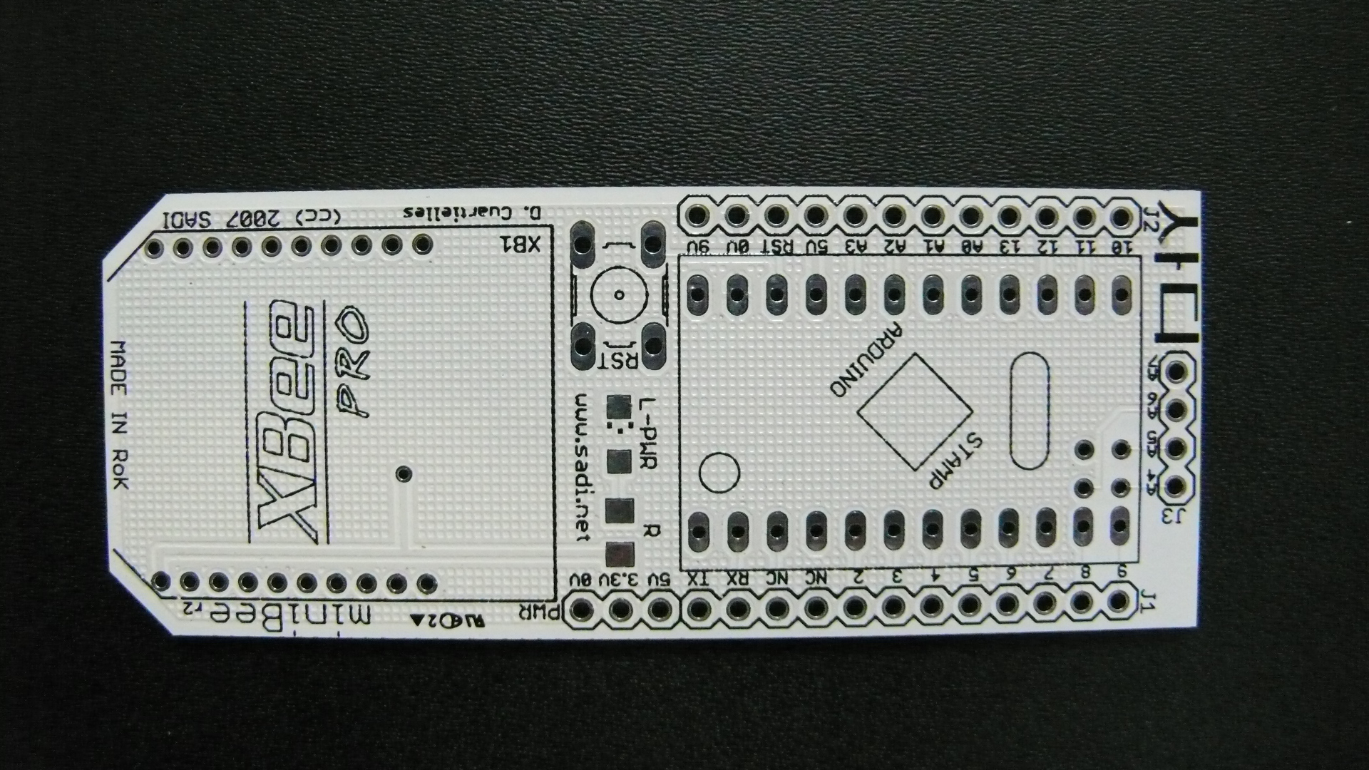
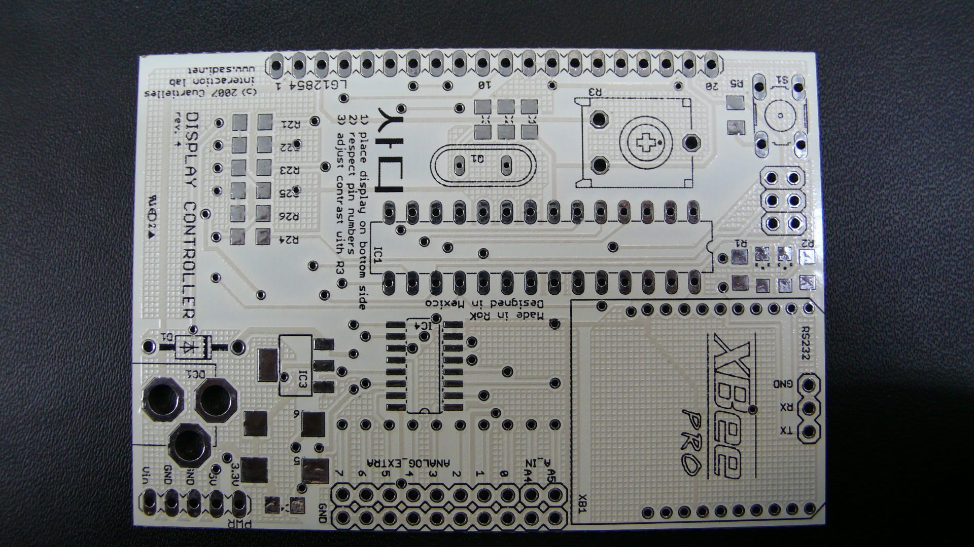
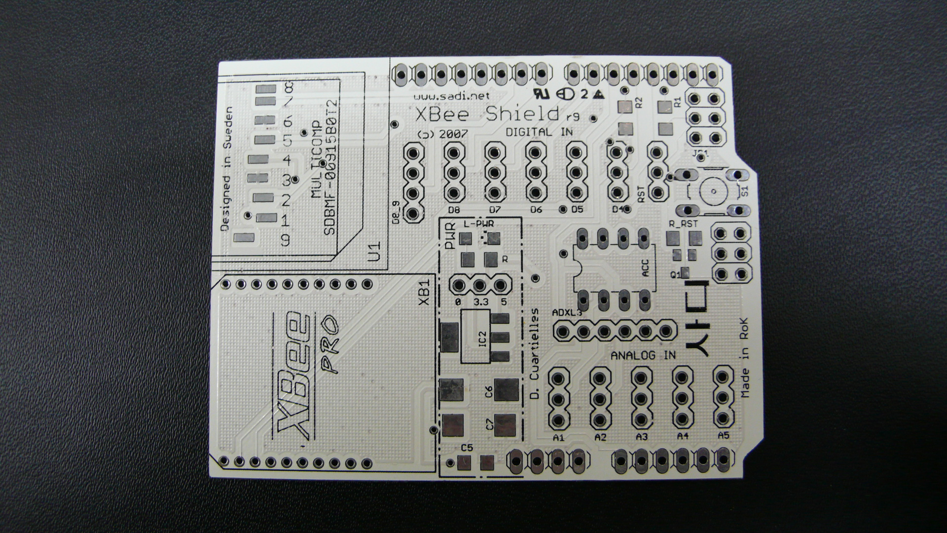
Sadi 인터랙션 디자인 연구소는 Sadi에 특화된 인터랙션 디자인 교육 프로그램을 연구하고, 인터랙션 디자인 작품 제작 활동을 지원하기 위하여 2007년 봄 Sadi 내에 개설된 부설 연구소이다.
Sadi 인터랙션 디자인 연구소는 지금 현재 Arduino 보드를 기반으로 피지컬 컴퓨팅 교육 프로그램을 개발, 운영하고 있으며, 향후 인터랙티브 제품 개발을 위한 교육 모듈의 개발 및 보급을 주요 목적으로 하고 있다.
이를 위하여 Sadi 인터랙션 디자인 연구소는 다음과 같은 활동 계획을 수립하여 추진해 나갈 예정이다.
첫째: Sadi Open Laboratory를 매주 목요일 오후 7시에 개최하고, 외부 인터랙티브 디자이너들을 초청하여 정기적인 세미나를 진행할 예정이다. 주제는 HCI (Human-Computer Interaction), CG (Computer Graphics), VR (Virtual Reality), 인터페이스 디자인, 사운드 디자인, 햅틱 디자인 등 다양한 주제를 광범위하게 다룰 예정이며, 매주 진행될 세미나는 본 웹사이트를 통하여 2~3일 전에 공지될 예정이다.
누구나 무료로 참여할 수 있으며, 누구라도 자신의 포트폴리오를 가지고 세미나 진행자가 될 수 있다. 단, 참여를 희망하는 사람은 cakepower@gmail.com 으로 사전등록을 해주기만 하면 된다.
둘째, 학과간 digital 이라는 공통 분야를 묶어, 다학제간 연계프로젝트를 개발, 운용할 계획이다.
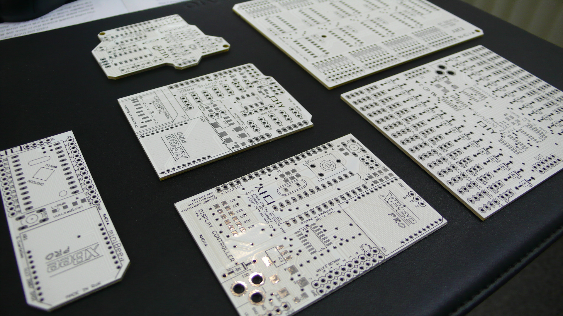
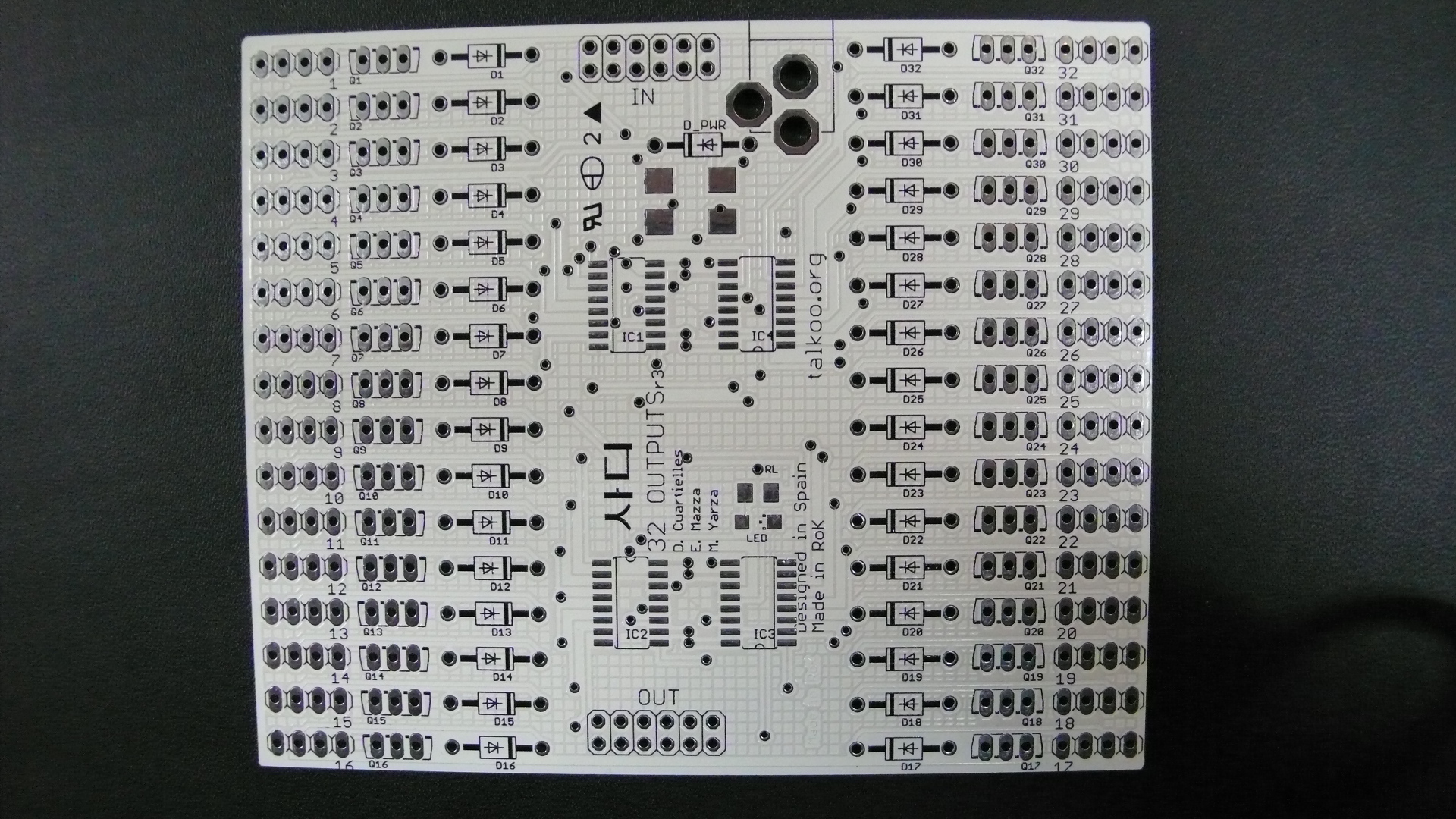
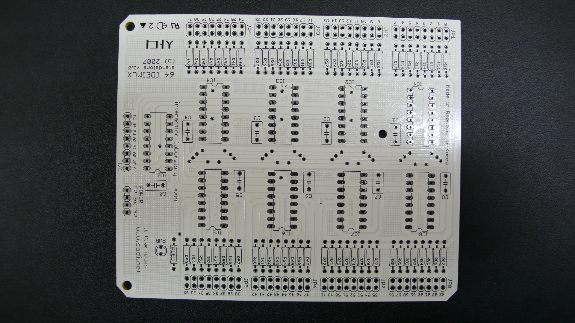
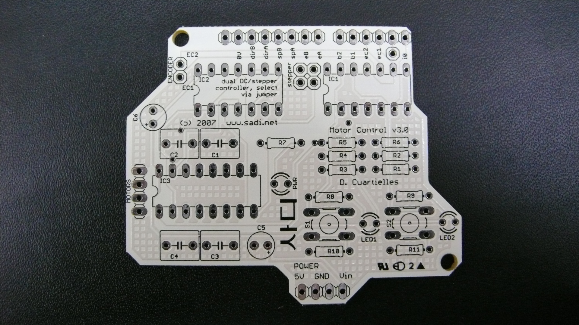
셋째, 인터랙션 관련 프로젝트 진행 시 필요한 working prototype용 모듈을 개발, 보급, 운용 지원할 예정이다.
넷째, 진행된 프로젝트를 아카이브 형식으로, 언제든지 학생들이 볼 수 있도록 웹사이트를 운용할 예정이다.
마지막으로, 국제적인 미디어 랩과 교류를 추진하고, 정기적인 공동 세미나를 유치할 예정이다.